From: Allen Thomson (thomsona@flash.net)
Subject: Re: Polaris Chevaline?
Newsgroups: sci.military.naval
Date: 2003-07-27 15:22:38 PST

This thread has inspired me to do something that I've been thinking
of for a while: make available the information about Chevaline that
came my way  back in the '90s.  What follows is pretty clearly
somebody's extraction of unclassified pages from a larger report or
reports, hence the general messiness.

I speculate that this material, which came from a US source, may be
associated with interest in buying second-hand Chevalines from the UK
for use as target dispensers in missile defense tests.

Pages are separated by ----- lines.  I've made an attempt to preserve
the page lay-out and appearance, but there's a limit to what you can
do in ASCII.

My comments and descriptions are in [square brackets].
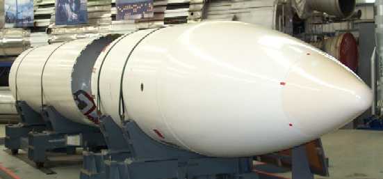
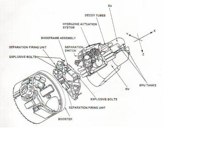
All photos with permission from http://www.skomer.u-net.com/projects/chevaline.htm---------------------------------------------------------------------- Unclassified US/UK BALLISTIC PAYLOAD CARRIER SYSTEM This Carrier System is developed from a proven UK Weapon System and consists of a fly-away Bus mounted on a baseframe. It is capable of being flown on a variety of US boost rockets. The Bus is a stable, manoeuvering platform which can be used for the controlled deployment of re-enty payloads or other ejectables exo-atmosphere, in variable sequence depending upon the mission objectives. Post-separation systems on board the Bus control navigation, stabilisation and event sequencing. The System has had full approval for in-service use aboard UK Submarines and is supported by a series of over forty-five fully instrumented flights including from the pad at AFETR, Cape Canaveral. This system and all the necessary supporting equipment is presently housed at Kirtland Air Force Base under the control of Field Command - Defense Special Weapons Agency. Page 1 Unclassified --------------------------------------------------------------------- DGSWS 5820 [stamped] UNCLASSIFIED ISSUE 2 ORIGINAL [Picture of bus looking from above and to the side. Shows two RVs, one fully, one partially. The one that can be seen best appears to have some sort of fabric wrapping, leaving only the hemispherical nose cap uncovered. Lables on the picture are "Attitude Control Thrusters," "Decoy Tubes" and "Bus Propulsion Unit."] 2-46 FIGURE 2-44 RES MATED -Y SIDE [stamped] UNCLASSIFIED DOWNGRADED IN ACCORDANCE TO VAX113/207/ACT(327) D/MOD SY(S&T)/3/4/3/APPENDIX A67 [handwritten]GW NO:1017675 [squiggle, apparently initials] [handwritten date] 25/9/96 --------------------------------------------------------------- Unclassified PHYSICAL CHARACTERISTICS BUS STRUCTURE The Bus structure comprises an aluminum closed torsion box with top and bottom diaphragms, strengthened by vertical divider plates. A steel base plate provides a payload mounting ring, baseframe attachment points, and mountings for separation rocket motors and the Space Reference Unit. Thermal skins protect the Bus components from residual exit heating effects after nose fairing eject. The BUS [sic] has integral lifting points to aid assembly. Approximate Weights and Dimensions: Overall Carrier length: 1.82 meters 72 inches Overall Carrier diameter: 1.37 meters 54 inches Maximum Carrier mass: 735 kg 1620 lb (including all payloads) Overall Bus length: 1.27 meters 50 inches Overall Bus diameter: 1.22 meters 48 inches Empty Bus mass: 318 Kg [sic] 700 lb (including fuels but less payload) Total Payload capacity: 400 Kg [sic] 880 lb BUS SUB-SYSTEMS Electronic Control Assembly (ECA) This electronic unit controls Bus initiation, guidance and event sequencing and has multiple levels of protection against disruption (circumvention). Within its Titanium alloy casing it comprises ; (i) Power Supply Unit providing DC and AC power up to 200V rms., (ii) Guidance Control Computer (hardened with power failure core store recovery and with programmable missions held in EEPROM) and (iii) Interface Control Unit initiating up to seventy-two ordnance or non-ordnance events. Space Reference Unit (SRU) Provides 3-axes attitude, rate and acceleration data to the ECA. The rate gyroscopes and accelerometer are fixed to the SRU body and the attitude gyros are caged with reference to the attitude of the vehicle at Bus separation and all data can be considered incremental from that datum. Bus Propulsion Unit (BPU) Main propulsioin of the Bus is produced by this high thrust hypergolic liquid rocket motor (fuel MAF-1/oxidant IRFNA). It provides 6300 N mean thrust (total impulse 77,500 Ns), which can be expended in multiple manoeuvers. Two nozzles (adjustable) provide different thrust lines to cater for major c.of g. shifts during a mission. The BPU features secondary containment of the liquids and is supplied fully fuelled. Page 3 Unclassified -------------------------------------------------------------------- [Line drawing showing top of booster, mounting unit and main PBV assembly.] [Lables are] [On booster]: "BOOSTER" [On mounting unit]: "BASEFRAME ASSEMBLY" "SEPARATION FIRING UNIT" "EXPLOSIVE BOLTS" "SEPARATION FIRING UNIT" "EXPLOSIVE BOLTS" [On PBV]: "SEPARATION SWITCH" "HYDRAZINE ACTUATION SYSTEM" "DECOY TUBES" "RV" "RV" "BPU TANKS" [There are XYZ coordinate axes in front of the PBV: X is along the line of flight, Z goes though the line of centers of the RVs, and Y is, of course, perpendicular to those two.] ----------------------------------------------------------------- DGSWS 5820 [stamped] UNCLASSIFIED ISSUE 2 ORIGINAL [This is a picture similar to the middle one at the bottom of http://www.skomer.u-net.com/projects/chevaline.htm. Instead of the E.E.E. sign in the dark part of the RV hollow there's one in the shiny part just above that has "1062" in big numbers and some smaller text that I can't make out.]
                                   [stamped UNCLASSIFIED]

                    FIGURE 2-14   +Z  'C'  CONE

2-16                                           VAX113/20/ACT(327)

                    DOWNGRADED IN ACCORDANCE TO
                    D/MOD SY(S&T)/3/4/3/APPENDIX A67

              [Initials]

--------------------------------------------------------------------

[seems to be cropped a little at the top]
[stamped UNCLASSIFIED]
ISSUE 2
ORIGINAL

[Picture somewhat similar to the left-hand one in
http://www.skomer.u-net.com/projects/chevaline.htm but taken from further
to the left and closer. The red tank is labled "Hydrazine Tank" and the
things under it are labled "Thermal Batteries." The box to the right of
the tank that's labled DL/CT in the Web picture is labled DB/C on in
the version I have.]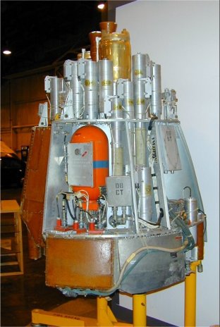
            FIGURE 2-32  -Y +Z THERMAL BATTERIES CONNECTED

                                            [STAMPED] UNCLASSIFIED

2-34                                                VAX113/20/ACT(327)

                         DOWNGRADED IN ACCORDANCE TO
                         D/MOD SY(S&T)/3/4/3/APPENDIX A67


      [Initials] [handwritten] 25/9/96

----------------------------------------------------------------------

DGSWS 5820                UK/US/EYES ONLY
ISSUE 2                      UK SECRET
ORIGINAL                    UNCLASSIFIED [stamped over above two
lines]

[Picture giving booster-eye view of bottom of PBV. Labels are]: "Attitude
Control Thrusters" "Bus Eject Motor" "Decoy Tubes" "Bus Eject Motor"
"Electronic Unit" "Safety/Arming Plugs"


FIGURE 2-16  -X BOTTOM DIAPHRAGM, ERMs [?] AND DECOYS INSTALLED

                             UK SECRET
                          UK/US EYES ONLY
                            UNCLASSIFIED [stamped over above two lines]

2-28
DOWNGRADED IN ACCORDANCE TO                    VAX113/207/ACT
D/MOD SY(S&T)/3/4/3/APPENDIX A67   [initials]

-----------------------------------------------------------------

                           Unclassified

                            PERFORMANCE

The Bus is a manoeuverable, stabilized vehicle capable of carrying and
ejecting (along pre-planned trajectories) up to 400 kg of payload during
flight. It was designed for the accurate targeting of RVs and exo-atmospheric
placement of pen-aids. It undergoes major displacements and turns
during a mission and is navigated by continuous velocity monitoring
with respect to an inertial reference established just prior to separation.

Utilising the Bus's accuate positioning capability, the dispersal of
objects can be in single or delayed burst modes to produce constellations,
trails, etc, during the exo-atmospheric portion of Bus flight.

FLIGHT TIME

The Bus has onboard thermal batteries which are normally initiated
immediately prior to separation from the booster. These batteries
give the Bus a typical powered flight time of 9 minutes.

Events may be operated later in flight by the use of self powered
firing circuits initiated by a trigger from the ECA.

By the use of additional battery power Bus operations can be extended
up to 20 minutes (governed by hydrazine fuel utilisation).

SEPARATION FROM BOOSTER

The Bus is normally separated from the booster using two solid eject
rocket motors which have a thrust of 24000 N each, imparting a
velocity of 30 m/s with respect to the booster.

Use of soft separation by means of hydraulic rams can give a typical
separation velocity of 5 m/s.

IN-FLIGHT VELOCITY CONTROL, STABILITY AND ACCURACY

During free flight, changes in the velocity of the Bus are achieved
by use of the liquid fuelled BPU. This motor has a mean thrust of
6300 N and a total impulse of 77,500 Ns, and can change the Bus
velocity by up to 0.2 km/s. The BPU is capable of multiple operations
and can be used to control the velocity of the Bus to within 0.1 m/s

The Bus is stabilised in flight by a 3-axis attitude control system
utilising dual level hot gas thrusters. This provides 360 deg steering
in pitch, +/-30 deg steering in yaw and can be controlled
+/-70 deg in roll.
The mean steady state attitude error is typically 0.1 deg under no
load conditions, 0.2 deg during ejection of lightweight object groups
and 0.3 deg during a main engine burn. Following major asymmetric
transient loads, such as RV ejection, the attitude recovers to nominal
within 2 seconds.

The Bus is mass balanced such that the c.of g. always lies within
its stabilisation control box.  The gross changes in the c. of g.
which occur during flight are adequately catered for through
corresponding changes to the control system parameters.


                             Page 5
                          Unclassified

-----------------------------------------------------------------


Bus Propulsion Unit

[Very poor-quality picture]

A bi-propellant engine providing thrust for gross manoeuvring of the
vehicle in flight. Driven by hot has from the hydrazine actuation
system, it comprises two thrust chambers fed from a pair of tandem
oxidant (nitric acid) and fuel (MAF-1) piston tanks.

It provides velocity increments for the BUS [sic] up to 0.2km/sec.

- 6300 N axial thrust (77,500 NS total impulse)

- Velocity control achieved to within 0.1m/sec.

- Fuel flow rate whan firing 2.5kg/sec.


------------------------------------------------------------------

                           Unclassified

                   ENVIRONMENTAL CHARACTERISTICS

The Carrier is a rugged system - designed to meet operational requirements
over a long service life. Total through-life support with re-buy
and refurbishment has maintained the equipment at the bottom of the
failure-rate "bathtub" curve for an extended period. The shock
and vibration qualification test severities imposed for the A3 motors
included substantial margins which have proved adequate to encompass
the enviroments imposed by alternative boosters.

SHOCK

The Carrier has been approved to a shock requirement which equates
to a 1- in -500 probability of occurrence in-service.

LOW LEVEL FLIGHT SHOCK

Half-sine shock levels covering low level flight shock events such
as booster ignition
                        33g for 35 ms along the X axis
                        10g for 35 ms along the Y and Z axis

HIGH LEVEL FLIGHT SHOCK

The most severe shocks for items mounted on the Bus and Baseframe
are those arising from the operation of the Bus Separation System.
The Carrier has been approved using the following levels of high
level shock:


                        [Begin table]

Structural Zone                        "g"            Duration (ms)

Units mounted on the baseframe,       1000               0.25
base structure and lower half          300               0.75
of the base structure

BPU and units mounted on the           300               0.25
Bus lower diaphragm and the ribs       125               1.00
above the lower diaphragm

Equipments mounted on the top          125.00            1.00
diaphragm

                        [End table]


VIBRATION

The vibration levels utilised in the design and test of the Carrier
equate to a 1-in- 44 probability of the occurrence.

The complete Carrier was designed to be subjected to random vibration
of 0.005 g^2/Hz +/- 3 dB at 20Hz increasingly linearly to 0.03 g^2/Hz
at 500Hz, and 003g^2/Hz over 500Hz to 2kHz, for 40 secs in each of
the 3 missile axes in turn, the levels being controlled at the baseframe.

The majority of carrier components and equipment have been tested to
a "Component" requirement of 0.15 g^2/Hz +/- 3 dB over 20 Hz to
2 kHz for 30 secs in all axes. Equipment not tested to this "Component"
requirement was separately reviewed and found to have substantial margins.


                            Page 7
                          Unclassified

--------------------------------------------------------------------

                          Unclassified

                            SAFETY

General

The Carrier is equipped with a series of mechanical and electrical
safety breaks.  The assembly has been designed so that it will fail
safe should a component failure occur.

Safety Features

The bus is fitted with Safety Plugs for ground handling and processing
which isolate both the pre- and Post-separation power supplies and
must be replaced by Arming Plugs before the mission.

Pre-separation power supply produced in the ECA is safeguarded by pairs
of open contacts on 2 gravity/time sensor switches, each switch
using a different mechanical damping system.

Protection against inadvertent operation of the ordnance is provided
by the use of distribution boxes employing opto- electronic isolation
modules which give complete electrical and physical isolation between
the trigger inputs and outputs.  Radio Frequency Attenuation
Connectors (RFACs) transfer the trigger energy to Type E fuseheads
whilst isolating them from other possible sources of energy.

The liquid systems incorporate primary and secondary containment plus
many other safety features, such that at least three unlikely events
would need to occur before the system can be pressurized.

Safe Monitoring

It is possible, subject to operational requirements, to establish
the state of each substantive safety break by visual examination or
safe electrical testing.


                           APPROVALS

Eastern Space and Missile Center has granted range safety approval
against ESMC Regulation 127-1 for operations at the Eastern Test Range
(ETR) during three phases of the UK In-Service programme:

 (a) Flat Pad launches of developmental hardware (1978 - 1980)
 (b) Submarne launches of Acceptance standard hardware (1980
            - 1982)
 (c) Submarine launches of Procuction standard hardware (1982
            - 1987)

These approvals include all operations from assembly to launch of the
Carrier.

Outline approval for use of an adaptation of the In-Service system
for launch from NASA, Goddard Space Flight Centre, Wallops Flight
Facility, Va has been granted under GSFC/WFF Range Safety Manual RSM-93.
This approval covers the use of a rail pad launch.

All explosive items have special to type containers with UN clearance
for transport by road and air.

                               Page 9
                            Unclassified


----------------------------------------------------------------------
From: Allen Thomson (thomsona@flash.net)
Subject: Polaris Chevaline?
Newsgroups: sci.military.naval
Date: 2003-12-30 16:50:47 PST

From the Google-cached version of
http://www.insys-ltd.co.uk/space/capabilities/capabilities.htm

  Strategic Systems

  Involvement in the UK's strategic and tactical nuclear weapons
  over several decades culminated in INSYS's appointment to the
  role of Design Authority for the complex Chevaline Penetration
  Aid Carrier (PAC), during the 1970's UK Polaris Improvement
  Programme. The PAC was a sophisticated autonomous spacecraft
  with guidance, 3-axis stabilisation and propulsion. Following a
  successful series of development and acceptance flights, this
  entered service with the Royal Navy in the early 1980's.

  In addition to full development and production responsibilities
  for the PAC, INSYS exercised major responsibilities for systems
  aspects associated with the Chevaline project, concerned with
  mass monitoring and control, rocket plume modelling, sub-system
  alignment, structural modelling and separation/trajectory
  modelling. INSYS personnel were members of the analysis teams
  sent to the US in support of all the development and in-service
  flight tests.

  From our background and expertise on the Chevaline, INSYS
  was in an excellent position to work on behalf of the UK MOD in
  many aspects of the successor ballistic missile system, Trident.
  Wide-ranging research and more specific studies were conducted
  into Trident re-entry performance. Of particular interest is the
  assessment of re-entry behaviour taking into account the effects
  of asymmetric aerodynamics caused by ablation and erosion. A
  legacy from this work was the capability in hypersonic
  aerodynamics and the state-of-the-art modelling tools for
  re-entry behaviour. A complete suite of software is available
  associated with the re-entry performance prediction methodology
  developed by INSYS.

  Exo-atmospheric Flight Testing

  INSYS is the only UK company which regularly designs, develops
  and flies payloads for the US missile defence programme,
  currently the responsibility of the US Missile Defence Agency
  (MDA). This results from US recognition of the INSYS extensive
  database, and innovative concepts which complement the US
  activities.

  Combining the expertise developed in strategic systems with its
  engineering and maunufacturing capability INSYS became the UK
  Principal Contractor for the provision of a sophisticated payload
  on a major UK/US collaborative re-entry vehicle flight experiment,
  flown on the US STARS booster from Barking Sands launch facility
  on Kauai. The Contract carried out for DERA (now Dstl), Farnborough
  involved the design, manufacture, development and qualification of
  the flight payload which included an instrumentation and telemetry
  package which provided exceptional flight dynamics data to analysts.
  INSYS Trials and Safety engineering disciplines were fundamental to
  the successful flight preparation activities during assembly,
  integration and test (AIT) and the flight campaign.

  During the same time period 1990 to 1993, INSYS were design
  authority for the provision of a number of experimental payloads
  to other US MDA exoatmospheric flight tests.

  Re-Entry Vehicles

  More recently INSYS has been awarded contract by Dstl, Farnborough
  as UK PC for the development of re-entry vehicles for the US
  missile defence community. INSYS work closely with US Space and
  Missile Defense Command who are the launch facilitators and other
  US sub contractors including Lockheed Martin, Coleman Aerospace/
  Orbital Sciences, Ball Aerospace and ITT Industries.

  Key to INSYS involvement in these programmes was its composite
  materials and precision manufacturing capability discussed later.

  The most recent flight test to include an INSYS designed and
  manufactured re-entry vehicle was in May 2002 when an RV target
  was provided for a US Patriot PAC3 intercept experiment.