 Auxiliary Dry Cargo Carrier (ADC(X))Auxiliary Dry Cargo Carrier (ADC(X))
CAGE Code XXX
DRAFT 18 MARCH 98
PERFORMANCE SPECIFICATION
SYSTEM SPECIFICATION
FOR THE
AUXILIARY DRY CARGO SHIP, T-ADC(X)
Prepared by:
Naval Sea Systems Command, SEA 03
2531 Jefferson Davis Hwy
Arlington VA, 22242-5160
SUBMITTED BY: __________________ DATE: ______________
Robert Draim
Executive Director
NAVSEA ENGINEERING DIRECTORATE
SEA 03B
APPROVED FOR USE AS A
FUNCTIONAL BASELINE BY: __________________ DATE: _____________
Doyle Kitchin, Captain U.S.N.
Program Manager, Support Ships, Boats and Craft
PMS 325
FSC 1915
DISTRIBUTION STATEMENT A: Approved for public release; distribution is unlimited.
1. SCOPE
1.1 Introduction.
1.2 Use.
2. APPLICABLE DOCUMENTS
2.1 General.
2.1.1 Government documents.
2.1.2 Specifications, standards, and handbooks.
2.1.3 Other Government documents, drawings, and publications.
2.2 Non-Government publications.
2.3 Order of precedence.
3. REQUIREMENTS
3.1 Mission.
3.2 Mission capabilities.
3.2.1 Description and quantity of cargo.
3.2.2 Cargo stowage and handling requirements.
3.2.3 Cargo loading and unloading rates.
3.2.4 CONREP station alignment.
3.2.5 CONREP station arrangement.
3.2.6 VERTREP facilities.
3.3 Other capabilities.
3.3.1 Mobility.
3.3.2 Survivability.
3.3.3 Command, control, and communications.
3.4 General requirements.
3.4.1 Regulatory body, classification and international regulations and requirements.
3.4.2 Design standards.
3.4.3 Design constraints.
3.4.4 Design objective.
3.4.5 Operating profiles.
3.4.6 External environment.
3.4.7 Reliability, maintainability, and availability (RMA).
3.4.8 Weight and stability.
3.4.9 Space and weight reservations (Navy communications).
3.4.10 Service life reserves.
3.4.11 Materials.
3.4.12 Human engineering.
3.5 System requirements.
3.5.1 Arrangements requirements.
3.5.2 Internal environment.
3.5.3 Structural requirements.
3.5.4 Machinery system requirements.
3.5.5 Electrical systems.
3.5.6 Interfaces.
3.5.7 Interior communications.
3.5.8 Pollution control.
3.5.9 Aviation support.
3.5.10 Boats.
3.5.11 Mooring gear.
3.5.12 Human support.
3.5.13 Security.
3.5.14 Designation and marking.
3.5.15 Electromagnetic environmental effects.
3.6 Logistics support requirements.
3.6.1 Supply support.
3.6.2 Maintenance.
3.6.3 Facilities.
3.6.4 Outfitting.
3.6.5 Standardization.
3.6.6 Computer resources.
3.7 Personnel.
4. VERIFICATION
4.1 Mission.
4.2 Mission capabilities.
4.2.1 Description and quantity of cargo.
4.2.2 Cargo stowage and handling requirements.
4.2.3 Cargo loading and unloading rates.
4.2.4 CONREP station alignment.
4.2.5 CONREP station arrangement.
4.2.6 VERTREP facilities.
4.3 Other capabilities.
4.3.1 Mobility.
4.3.2 Survivability
4.3.3 Command, control, and communications.
4.4 General requirements.
4.4.1 Regulatory body, classification and international regulations and requirements.
4.4.1
4.4.2 Design standards.
4.4.3 Design constraints.
4.4.4 Design objective.
4.4.5 Operating profiles.
4.4.6 External environment.
4.4.7 Reliability, maintainability, and availability (RMA).
4.4.8 Weight and stability.
4.4.9 Space and weight.
4.4.10 Service life reserves.
4.4.11 Materials.
4.4.12 Human engineering.
4.5 System requirements.
4.5.1 Arrangements requirements.
4.5.2 Internal environment.
4.5.3 Structural requirements.
4.5.4 Machinery system requirements.
4.5.5 Electrical systems.
4.5.6 Interfaces.
4.5.7 Interior communications.
4.5.8 Pollution control.
4.5.9 Aviation support.
4.5.10 Boats.
4.5.11 Mooring gear.
4.5.12 Human support.
4.5.13 Security.
4.5.14 Designation and marking.
4.5.15 Electromagnetic environmental effects.
4.6 Logistics support requirements.
4.6.1 Supply support.
4.6.2 Maintenance.
4.6.3 Facilities.
4.6.4 Outfitting.
4.6.5 Standardization.
4.6.6 Computer resources.
4.7 Personnel.
5. PACKAGING
5.1 Packaging.
6. NOTES
6.1 Definitions.
6.1.1 Allocated baseline weight estimate.
6.1.2 Connected replenishment.
6.1.3 Easily removable.
6.1.4 FAILSAFE.
6.1.5 Government.
6.1.6 Guidance.
6.1.7 Multi-purpose.
6.1.8 Regulatory body.
6.1.9 Ship loading conditions.
6.1.10 Standardization.
6.1.11 Trials.
6.1.12 Underway replenishment.
6.1.13 Vertical replenishment.
6.1.14 Voyage repair.
6.2 List of acronyms.
FIGURES
FIGURE 1. CONREP station alignment.
TABLES
TABLE I. Cargo loadouts.
TABLE II. Performance requirements for various sea states.
TABLE III. Stores endurance.
TABLE IV. Additional A-60 structural fire protection.
TABLE V. Ship dimensional constraints.
TABLE VI. Speed time operating profile.
TABLE VII. Sea, wind, and current conditions.
TABLE VIII. Ship operating temperatures.
TABLE IX. Quantitative reliability and availability.
TABLE X. Space and weight reservations (Navy communications).
TABLE XI. Solid waste generation rate estimates
TABLE XII. Air emissions standards.
TABLE XIII. Minimum area requirements for staterooms.
TABLE XIV. Minimum area requirements for sanitary spaces.
TABLE XV. Minimum area requirements for lounges.
TABLE XVI. Minimum area requirements for offices.
TABLE XVII. Shipboard external EME for systems and ordnance.
APPENDICES
APPENDIX A UNREP OPERATIONAL TEMPOS
APPENDIX A1 AMMO UNREP OPERATIONAL TEMPO - 1 64
APPENDIX B CARGO LOAD LISTS
APPENDIX B1 CARGO AMMUNITION LOAD LIST 66
APPENDIX C UNREP LISTS
APPENDIX C 1 CV AMMUNITION UNREP LIST - A 69
APPENDIX D INTERSHIP TRANSFER RATES FOR CONREP AND VERTREP
APPENDIX E MILITRY SEALIFT COMMAND MAINTENANCE PHILOSOPHY
Logistics support is a basic need of any fighting force, and it must be maintained and modernized to remain viable. For Naval forces, logistical support requires a capability to re-supply at sea by means of replenishment ships. The purpose of the Auxiliary Dry Cargo Ship (T-ADC(X)) is to replace the cargo lift and transfer capability of the T-AE 26, T-AFS 1, and T-AFS 8 Class ships.
This specification is a description of the system requirements for T-ADC(X). Included are the mission, capabilities, major systems requirements, interfaces, environmental constraints, interchange requirements, logistics concept, personnel, and verification requirements.
This specification establishes overall system requirements to guide the subsequent engineering development and more detailed specifications.
Some Combat Logistics Force (CLF) ships (station ships) are integral parts of the surface battle groups and others (shuttle ships) move logistical supplies from ports, forward logistics sites, or commercial ships (black hulls) to the battle group at sea. T-ADC(X) will be primarily a shuttle ship, providing logistics lift from sources of supply to station ships and other ships operating with Naval forces. Additionally, T-ADC(X) may be required to operate in company with a T-AO 187 Class ship while performing a station ship role. T-ADC(X) must be fully inter-operable with all U.S. Navy and North Atlantic Treaty Organization (NATO) ships capable of underway replenishment.
The documents listed in this section are specified in sections 3 and 4 of this specification. This section does not include documents cited in other sections of this specification or documents referenced for guidance, for additional information, or as examples. While every effort has been made to ensure the completeness of this list, document users are cautioned that they must meet all specified requirements documents cited in sections 3 and 4 of this specification, whether or not they are listed.
The following specifications, standards, and handbooks of the exact revision listed below form a part of this document to the extent specified herein.
STANDARDS
DEPARTMENT OF DEFENSE
MIL-S-901D Shock Tests, H.I. (High Impact)
(17 March 1989) Shipboard Machinery, Equipment, and Systems, Requirements for
(Unless otherwise indicated, copies of the above specifications, standards, and handbooks are available from the Standardization Documents Order Desk, 700 Robbins Avenue, Building 4D, Philadelphia, PA 19111-5094.)
The following other Government documents, drawings, and publications of the exact revision level shown form a part of this document to the extent specified herein.
DEPARTMENT OF THE NAVY
DRAWINGS
NAVSEA 802-6337553 T-ADC(X) UNREP Station Arrangement
NAVSEA 802-6337556 T-ADC(X) Cargo/Weapons Elevator Arrangement
MANUALS
NAVSEA 0908-LP-000-3010 Shock Design Criteria for Surface Ships
(September 1995)
NAVSEA OP 2173 Approved Handling Equipment for Weapons and
(15 January 1994) Explosives; Adapters thru Jigs, W/CHGS 1-4
NAVSEA OP 4 Chg 18 Ammunition Afloat
(15 April 1995)
NAVSEA OP 3565 Electromagnetic Radiation
(15 December 1988) Hazards (Hazards to Ordnance)
NAVSEA SW023-AH-WHM-010 Handling Ammunition and Explosives with
(15 January 1996) Industrial Materials Handling Equipment (MHE)
OPNAVINST 5530.13 Physical Security Instructions for
(5 July 1994) Conventional Arms, Ammunitions and Explosives (AA&E)
OPNAVINST C8950.2 Magnetic Silencing
(20 August 1990)
(Copies of the above manuals are available from the Standardization Documents Order Desk, 700 Robbins Avenue, Building 4D, Philadelphia, PA 19111-5094.)
DESIGN DATA SHEET (DDS)
DDS 130-2 Structural Design and Analysis of Helicopter Handling Decks
(Copies of the above Design Data Sheet are available from the Naval Sea Systems Command, SEA 03R4, 2531 Jefferson Davis Hwy, Arlington ,VA 22242-5160.)
NAVAL AIR SYSTEMS COMMAND (NAVAIR)
Bulletin No. 1H (3 March 1997) Air Capable Ship Aviation Facilities
(Applications for copies should be addressed to Commanding Officer, Naval Air Technical Service Facilities, 700 Robbins Avenue, Philadelphia, PA 19111-5097.)
SOFTWARE
SMP 95 U.S. Navy Ship’s Motions Program
(Copies of the above software are available from the Naval Sea Systems Command, PMS 325, 2531 Jefferson Davis Hwy, Arlington , VA 22242-5160)
DEPARTMENT OF TRANSPORTATION (DOT)
DOT Hazardous Materials Regulations
USCG REGULATIONS
CFR Title 33 Navigation and Navigable
(Version in effect at delivery) Waters
CFR Title 46 Shipping
(Version in effect at delivery)
NAVIGATION AND VESSEL INSTRUCTIONS CIRCULAR (NVIC)
NVIC 12-82 (1 June 1982) Recommendations On Control of Excessive Noise
(Application for copies should be addressed to the Superintendent of Documents, U.S. Government Printing Office, Washington, DC 20402-0002.)
DEPARTMENT OF HEALTH AND HUMAN SERVICES
PUBLIC HEALTH SERVICE
Publication No. 68 (1963) Handbook on Sanitation of Vessels in Operation - Sanitation Features and Facilities on Vessels in Operation
Publication No. 393 (1965) Handbook on Sanitation of Vessel Construction
(Application for copies should be addressed to the Superintendent of Documents, U.S. Government Printing Office, Washington, DC 20402-0002.)
The following document(s) of the exact revision listed below form a part of this document to the extent specified herein.
AMERICAN BUREAU OF SHIPPING (ABS)
ABS Rules for Building and Classing Steel Vessels (1997)
ABS Guide for One Man Bridge Operated (OMBO) Ships (1992)
ABS Guide for Survey Based on Preventive Maintenance Techniques (1995)
ABS Guide for Underwater Inspection in Lieu of Drydocking Survey (1996)
ABS Guide for Thrusters and Dynamic Positioning Systems (1994)
ABS Guide for Cargo Vapor Emission Control Systems on Board Tank Vessels (1991)
(Application for copies should be addressed to the American Bureau of Shipping, Corporate Publications Department, Two World Trade Center, 106th Floor, New York, NY 10048.)
AMERICAN PETROLEUM INSTITUTE (API)
API 2c (3 April 1995) Specification for Offshore Cranes
(Application for copies should be addressed to the American Petroleum Institute, 1220 L Street, NW, Washington, DC 20005.)
AMERICAN SOCIETY OF MECHANICAL ENGINEERS (ASME)
A17.1 (3 October 1996) Safety Code for Elevators and Escalators
(Application for copies should be addressed to the American Society of Mechanical Engineers, 345 E 47th Street, New York, NY 10017.)
AMERICAN SOCIETY FOR TESTING AND MATERIALS (ASTM)
ASTM D189 (1 January 1995) Standard Test Method for Conradson Carbon Residue of Petroleum Products
ASTM D445 Standard Test Method for Kinematic Viscosity of Transparent and Opaque Liquids (the Calculation of Dynamic Viscosity)
ASTM D524 (1 January 1995) Standard Test Method for Ramsbottom Carbon Residue of Petroleum Products
ASTM D664 (1 January 1995) Standard Test Method for Acid Number of Petroleum Products by Potentiometric Titration
ASTM D874 (1 January 1996) Standard Test Method for Sulfated Ash from Lubricating Oils and Additives
ASTM D893 (1 January 1992) Standard Test Method for Insolubles in Used Lubricating Oils
ASTM D 975 (10 November 1996) Standard Specification for Diesel Fuel Oils
ASTM D2982 Standard Test methods for Detecting Glycol-Base Antifreeze in Used Lubricating Oils
ASTM D4739 Standard Test Method for Base Number Determination by Potentiometric Titration
ASTM F 1166 Standard Practice for Human Engineering Design
(10 November 1995) for Marine Systems, Equipment and Facilities
(Application for copies should be addressed to the American Society for Testing and Materials, 100 Barr Harbor Drive, West Conshohocken, PA 19428-2959.)
INSTITUTE OF ELECTRICAL AND ELECTRONICS ENGINEERS (IEEE)
IEEE P45/D2.0 (June 1997) Draft Recommended Practice for Electric Installations on Shipboard
IEEE C95.1 (26 September 1991) Standard for safety levels with respect to human exposure to radio frequency electromagnetic fields, 3kHz to 300 MHz
(Application for copies should be addressed to the Institute of Electrical and Electronics Engineers, 445 Hoes Lane, PO Box 1331, Piscataway, NJ 08855-1331.)
INTERNATIONAL MARITIME ORGANIZATION (IMO)
IMO-200E (1994) International Maritime Dangerous Goods Code (IMDG Code)
IMO-210E (1 January 1997) IMDG Code Supplement
MARPOL (1997) International Convention for the Prevention of Pollution from Ships
SOLAS (1997) International Convention for the Safety of Life at Sea
(Application for copies should be addressed to the Publication Section IMO, 4 Albert Embankment, London SE1 7SR, UK.)
INTERNATIONAL ORGANIZATION FOR STANDARDIZATION (ISO)
ISO 2314 Gas Turbines - Acceptance Tests
ISO 3046-2 Reciprocal Internal Combustion Engines - Performance. Part 2: Test Methods
ISO 6954 (15 December 1984) Mechanical Vibration and Shock Guidelines for the Overall Evaluation of Vibration in Merchant Ships. First Edition
ISO 8217 (15 March 1996) Petroleum Products - Fuels (class F) - Specifications of Marine Fuels. Second Edition
(Application for copies should be addressed to the International Organization for Standardization, Case Postale 56, Geneva, Switzerland CH-1211.)
NATIONAL FIRE PROTECTION ASSOCIATION (NFPA)
NFPA 750 (1996) Standard for the Installation of Water Mist Fire Protection Systems
(Application for copies should be addressed to NFPA, Batterymarch Park, PO Box 9101, Quincy, MA 02269-9101)
SOCIETY OF NAVAL ARCHITECTS AND MARINE ENGINEERS (SNAME)
T & R Bulletin No. 3-28 Marine Gas Turbine Power Plant Performance
(July 1976) Practices
T & R Bulletin No. 3-47 (1989) Guide for Sea Trials
T & R Bulletin No. 3-49 Marine Diesel Power Plant Practices
(June 1990)
T & R Bulletin No. 4-16 Recommended Practices for Merchant Ship
(August 1980) Heating, Ventilation and Air Conditioning Design Calculations
T & R Code C-5 Acceptable Vibration of Marine
(September 1976) Steam and Heavy Duty Gas Turbine Main and Auxiliary Machinery Plants
(Application for copies should be addressed to the Society of Naval Architects and Marine Engineers, 601 Pavonia Avenue, Jersey City, NJ 07306.)
In the event of a conflict between the text of this specification and the references cited herein, the text of this specification takes precedence. Nothing in this specification, however, supersedes applicable laws and regulations unless a specific exemption has been obtained.
The following are the systems requirements for the T-ADC(X), hereafter referred to as the ship.
The ship’s mission is to deliver a steady supply of ammunition; stores; petroleum, oil and lubricants; repair parts; and expendable supplies and material to Naval forces in various operational environments. The ship shall employ the Connected Replenishment (CONREP) method as well as Vertical Replenishment (VERTREP) to receive and deliver this cargo. The ship shall be capable of receiving and stowing retrograde material from customer ships including ordnance stowage containers, repairable electronic components, hazardous waste including biological waste, human remains in approved stowage containers, and material handling and packaging materials. The ship shall remain with the station ship if the tactical scenario does not allow Underway Replenishment (UNREP) consolidation on a prearranged schedule, or the ship may be required to act as a station ship.
The ship shall be capable of simultaneous UNREP of two customer ships alongside at speeds of 12-16 knots. Underway cargo handling and UNREP shall be capable of being performed both day and night. The ship without helicopters shall be capable of performing continuous self loading and self unloading, day and night, alongside a pier and at anchor in accordance with Table VII. Additional capabilities shall include:
Appendix B presents cargo load lists for different ship mission loadouts. The ship shall be capable of stowing and efficiently loading and unloading, individually, each of the three cargo loadouts described in Table I without reconfiguration of the ship:
|
Loadout type |
Dry cargo |
Liquid cargo |
Other cargo |
|
Ammunition |
Appendix B1 |
3975 m3 F76 or F44 Fuel 200 m3 Potable Water |
Specialty cargo |
|
Stores |
Appendix B2 |
3975 m3 F76 or F44 Fuel 200 m3 Potable Water |
Specialty cargo except pyrotechnics, white phosphorus, fuzes, primers, and detonators |
|
Mixed Ammunition & Stores |
Appendix B3 |
3975 m3 F76 or F44 Fuel 200 m3 Potable Water |
Specialty cargo |
The intra-ship material handling system shall permit the temporary stowage and movement of cargo at sea. Clearance from a fixed overhead obstruction to the top of stowed cargo shall be not less than 150 mm. Portable equipment, mobile handling equipment, tools, and accessories of the replenishment systems shall be stowed in locations convenient for their use. Cargo transfer and handling equipment and arrangements shall be provided to permit any packaged cargo unit to be moved from its stowage space to each CONREP or VERTREP location by not less than two means and two different routes (for example, two elevators per hold). Only one route needs to be provided to accommodate outsized cargo. Adequate clearances shall be provided in cargo routes to permit unrestricted movement of the largest cargo to be handled on that route. Clearance shall be not less than the following:
Cargo handling passageways between pre-staging areas, CONREP transfer stations, elevators, and the flight deck shall have a minimum clear width of 3.7 m. Unless otherwise specified, cargo spaces shall be provided with:
Where "chill" spaces are specified, the temperature of these spaces shall be capable of being automatically maintained at not greater than 2 degrees C. Where "freeze" spaces are specified, the temperature of these spaces shall be capable of being automatically maintained at not greater than minus 23 degrees C. For refrigerated spaces operating at temperatures above 0 degrees C, the suction line leaving the space shall be fitted with an evaporator pressure regulating valve to limit the normal operating evaporator pressure to a saturated evaporator temperature of a maximum of 11 degrees C below the space temperature setting. Control and monitoring of cargo space air conditioning and refrigeration shall be provided both remotely via the centralized machinery control system and locally.
An additional capability shall be provided to transfer potable water using a 65 mm hose suspended from the fueling rigs described above. The ship shall provide a potable water flow rate of 950 liters per minute at a riser pressure of 690 kPa.
The ship shall also be capable of transferring fuel through a 65 mm hose using the astern refueling method. The capability of transferring potable water through a 65 mm hose using the astern method shall also be provided. The transfer rate shall be adjustable so as to accommodate the rate at which the receiving ship can receive fuel or potable water. The ship shall be equipped to prevent pollution of the sea by minimizing residual fuel in hoses prior to disconnecting the fuel hose from the customer ship. The fuel oil tanks and system shall be so arranged that the quantity of fuel delivered and received from each station can be determined by direct measurement.
In order to provide alignment with the customer ships, adequate off-station angle capability, space for maneuvering cargo, and space for personnel to safely operate, the CONREP stations shall be located as shown in Figure 1.
In order to provide interchangeable UNREP equipment with the existing CLF ships, and provide all necessary interface requirements for all existing fleet customer ships, the CONREP station equipment shown in drawing, NAVSEA No. 802-6337553 shall be provided. Drawing, NAVSEA No. 802-6337553 shall be used to determine the relative positions of the various CONREP equipment. Additionally, this drawing’s sub-tier interface drawings shall be used to determine the range of equipment locating distances.
The VERTREP area shall be located aft in order to safely and efficiently interface with customer ships. The VERTREP deck shall be on the same level as the transfer deck and be directly accessible to and from the CONREP stations.
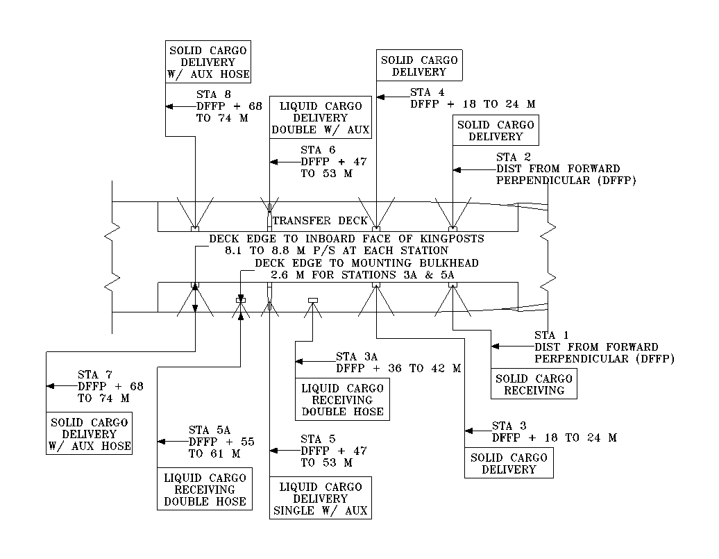
FIGURE 1. CONREP station alignment.
![]()
Where:
Fuel rate = kg/hr based on fuel with a lower calorific value of 42,000 kJ/kg, and ambient air and sea water temperatures of 38 degrees C and 32 degrees C, respectively
1.10 provides for 10 percent reserve
1000 is kg/metric ton
0.98 is the tailpipe allowance
Sustained speed is in knots
The propulsor(s), shafting, and other underwater appendages shall survive the marine environment at the speed-time profile specified with no visible erosion between scheduled drydockings. The propulsor design shall maximize propulsive efficiency and minimize cavitation at all steady ahead operating conditions consistent with other requirements. Means shall be provided for locking of shaft(s).
The thruster(s), if applicable, shall be capable of transitioning from maximum thrust in one direction to maximum thrust in the opposite direction in less than 12 seconds.
The ship shall be capable of rotating 180 degrees within 15 minutes without the use of the main propulsion system.
The ship shall be capable of lateral movement against a beam, bow quartering, and stern quartering wind of 20 knots, such as disengaging from dock
Inflow protection for the thruster(s), if applicable, shall be provided and designed to minimize degradation of ship speed performance.
TABLE II. Performance requirements for various sea states.
|
Ship |
Vertical |
Acceleration |
Deck |
|||||||||
|
Sea |
heading |
Speed |
Locations |
Roll |
Pitch |
velocity |
Vert. |
Lat. |
Long. |
wetness |
Slams |
|
|
Mission |
state |
(deg) |
(knots) |
of interest |
(deg) |
(deg) |
(m/s) |
(g) |
(g) |
(g) |
per hour (Note 7) |
per hour (Note 8) |
|
Survival |
8 |
all |
0 |
(Note 2) |
34 |
6 |
N/A |
0.4 |
0.2 |
0.25 |
30 |
20 |
|
Liquid cargo transfer |
5 |
(Note 1) |
12 to 16 |
(Note 3) |
5 |
1.5 |
N/A |
0.4 |
0.2 |
0.2 |
0 |
20 |
|
Solid cargo transfer |
5 |
(Note 1) |
12 to 16 |
(Note 4) |
4 |
1.5 |
N/A |
0.4 |
0.2 |
0.2 |
0 |
20 |
|
VERTREP |
5 |
(Note 1) |
12 to 16 |
(Note 5) |
5 |
3 |
2.0 |
0.4 |
0.2 |
0.2 |
0 |
20 |
|
Staging & strike-down |
6 |
all |
12 to 16 |
(Note 6) |
8 |
3.5 |
N/A |
0.4 |
0.2 |
0.2 |
30 |
20 |
GENERAL:
Values are Significant Single Amplitude.
NOTES:
|
Stores |
Days |
|
Dry |
90 |
|
Freeze |
90 |
|
Chill |
45 |
|
Repair |
90 |
|
Ships Store |
90 |
|
General stores material |
90 |
|
Lubricants and chemicals |
180 |
|
Medical |
90 |
|
Bottled gasses |
180 |
The ship shall meet the following survivability and vulnerability requirements:
Three damage control lockers shall be provided on the bulkhead deck: one forward of the cargo holds, one aft of the cargo holds, and one approximately amidships. Accessible stowage shall be provided for all DC equipment listed on the DC AELs. Each DC locker shall provide adequate stowage for DC equipment not placed in a distributed stowage configuration. NAVSEA S5090-B1-MMO-010 may be used for guidance. A rack for display of damage control diagrams (640 x 970 mm) and stowage for damage control documentation shall be provided. A compressor and refill station shall be provided for refilling high pressure, self contained breathing apparatus (SCBA).
TABLE IV. Additional A-60 structural fire protection.
|
Structure Protected |
Location |
|
Bulkheads between: |
1. Cargo holds 2. Cargo holds and fuel tanks 3. Machinery spaces and fuel tanks 4. Flammable liquids cargo spaces and other cargo spaces |
|
Decks between: |
1. Machinery spaces and storerooms 2. Machinery spaces and habitability spaces 3. Chart room and other interior spaces |
The primary ship control location shall be the Navigating Bridge, with secondary propulsion and thruster (if applicable) control from bridge wings, port and starboard. The command, control, and communications systems and equipment shall be in accordance with the requirements of the Regulatory Body requirements, Classifications Rules, SOLAS, and the ABS Guide for One Man Bridge Operated (OMBO) Ships.
The MCCS shall be designed for main control from the MCC and secondary control from the SCC. Transfer of control shall be accomplished by a request to the controlling console and an acknowledgment from the controlling console. During plant operation, the MCCS shall also continuously monitor and control: auxiliary plant temperatures, pressures, flows, and levels; electric plant characteristics; and damage control systems. Abnormal conditions shall actuate alarms to warn of the condition and provide for automatic shutdown in the case of malfunctions which could lead to equipment damage or personnel hazard.
Central data acquisition and display shall be incorporated as an integral part of the MCCS. Multiple color flat panel or CRT monitors shall be provided in the MCC and one color flat panel or CRT shall be provided in the SCC and Chief Engineer’s office for selective display of data items, alarms, and mimics. Color flat panels and CRTs shall be a minimum of 483 mm diagonal and shall be capable of being configured independently of each other to permit display of data, alarms, and mimic on different monitors simultaneously. Mimics shall dynamically display the status of machinery, valves, tank levels and controls on a schematic representation of the system.
Automatic data logging shall be provided to furnish a printed record of selected monitored parameters and associated alarm status every 4 hours, whenever the station in control of propulsion changes, and on demand. The data loggers shall also provide a record of alarmed parameters including date, time, alarm set or re-set, and maneuvering bell. A summary data log of selected plant status shall be printed automatically every 24 hours or on demand and shall be in the form similar to an engineer’s log book. An interface shall be provided for downloading data from the MCCS to a personal computer for data collection and trend analysis.
A separate bell logger shall automatically provide a printed record of SCC telegraph orders including date, time, standard order, ordered and actual rpm and pitch, (if applicable) and station in control. The bell and data loggers shall be identical.
MCCS equipment, including computer hardware and software, shall include provisions for at least 20 percent growth for future alarms and controls.
MCCS software shall be in an industry standard, high level, non-proprietary language. The system configuration shall permit the system user to change set point levels, add and delete equipment items to be monitored or controlled and to change the contents and format of the bell and data logger printed outputs. Means to prevent unauthorized tampering with MCCS software data and bell logs, and set points shall be provided.
The MCCS shall be capable to attach and communicate to the local area network (LAN) to download data via open database connectivity to an SQL compliant client/server database installed on the LAN. Data download shall be configurable for both timing and parameter download definition, including bell logging, alarm logging, alarm set or reset. Date and time stamping of all parametric and logging shall be incorporated.
In case of conflict between regulatory body, classification and international regulations and requirements, and this specification, the more stringent requirement shall take precedence.
The ship, as delivered, shall comply with the applicable laws of the United States and the requirements and rules of the various regulatory bodies for vessels used in non-public purposes, including those listed below:
The ship shall incorporate measures to permit extended periods between drydockings and shall be in accordance with the ABS Guide for Underwater Inspection in Lieu of Drydocking Survey.
The ship shall incorporate preventative maintenance measures and shall be in accordance with the ABS Guide for Survey Based on Preventive Maintenance Techniques.
The ship shall be in accordance with the ABS Guide for OMBO Ships.
Thrusters, if provided, shall be in accordance with the ABS Guide for Thrusters and Dynamic Positioning Systems.
The ship’s cargo vapor emission control system is to be in accordance with the ABS Guide for Cargo Vapor Emission Control Systems on Board Tank Vessels.
TABLE V. Ship dimensional constraints.
|
Maximum Length Overall |
210 m |
|
Maximum Breadth |
Maximum for routine transit of Panama Canal |
|
Maximum Navigational Draft |
9.5 m in salt water in the full load condition with service life allowance for displacement. |
|
Maximum Height of Fixed Structures |
41 m above the waterline in the minimum operating condition |
The total ship system shall be a balanced design that satisfies the ship’s requirements specified herein and is consistent with the ship’s concept of operations. The general design philosophy shall be to meet system performance requirements while minimizing life cycle cost. Since design in its simplest form can be described as an engineer’s response to a need, there are a multitude of design solutions which can respond to a given need. For assistance in trading-off these design solutions, the following design attributes are provided in descending order of importance:
When operating profiles are specified herein or are required for design or analysis, the following profiles shall be used. During at sea operations; for example, transit, UNREP, and other underway operations; the speed time profile of Table VI shall be used.
TABLE VI. Speed time operating profile.
|
Speed Range |
Percent of Time |
Average Speed, knots |
|
Drifting |
4 |
0 |
|
up to 7 knots |
7 |
4.6 |
|
8 to 11 knots |
13 |
9.7 |
|
12 to 14 knots |
26 |
13.1 |
|
15 to 17 knots |
20 |
15.9 |
|
18 knots and above |
30 |
19.4 |
Phase Description Total days Percent
1 Voyage repair period 14 16
2 In port (cargo XFR, refuel, training) 21 23
3 Underway replenishment 36 40
(Resupply of battlegroups)
4 Resupply from other ships 2 2
5 Transit 17 19
Total 90 100
Day 1 2-4 5 6-8 9 10-13 14 15-17 18 19 20-22 23 24-27
Phase 5 3 5 3 5 2 5 3 5 4 3 5 2
Day 28 29-31 32 33-35 36 37-40 41 42-44 45 46-48 49
Phase 5 3 5 3 5 2 5 3 5 3 5
Day 50-53 54 55-57 58 59-61 62 63-67 68 69-71
Phase 2 5 3 4 3 5 2 5 3
Day 72 73-75 76 77-90
Phase 5 3 5 1
b. Wartime. - This notional operating profile is a 26-day continuous wartime employment period.
Phase Description Total days Percent
1 In-port time (load, re-fuel, cargo ops,) 8 31
2 Transit 10 38
3 Underway replenishment 8 31
Total 26 100
TABLE VII. Sea, wind, and current conditions.
|
Performance requirements |
Environmental conditions |
|
UNREP (VERTREP, CONREP) |
Headings within 30° of head and following seas in sea state 5 (significant wave height of 4 m, all wave modal periods from 5 to 15 seconds, average wind speed of 24.5 knots). |
|
Staging and Strike-down |
All headings in sea state 6 (significant wave height of 6 m, all wave modal periods from 10 to 16 seconds, average wind speed of 37.5 knots). |
|
Continuous Efficient Operation (other than replenishment) |
All headings in sea state 6 (significant wave height of 6 m, all wave modal periods from 10 to 16 seconds, average wind speed of 37.5 knots). |
|
Survive without Serious Damage to Mission-Essential Systems |
All heading in sea state 8 (significant wave height of 14 m, all wave modal periods from 14 to 19 seconds, average wind speed of 63 knots). |
|
Load and unload cargo and stores alongside a pier |
All headings in seas with a significant wave height of 0.3 m, all wave modal periods from 3 to 15 seconds, and average wind speed of 15 knots with 30 knot maximum gusts. |
|
Load and unload cargo and stores at anchor |
Headings within 30° of head seas in seas with a significant wave height of 0.9 m, all wave modal periods from 5 to 15.5 seconds, average wind speed of 15 knots with 30 knot maximum gusts. |
|
Moored pierside |
Headings of 0º, 90º, and 180º in three knots of current and 50 knots of wind both tending to push the ship away from the pier. |
The sea states referred to above are those defined by the Bretschneider formulation. Wind shall be defined by the Davenport spectrum and average wind speed is taken at 19.5 m above sea level.
b. Temperature and humidity. - The ship and its systems shall be capable of getting underway, loading and off-loading cargo, UNREP operations, and operating in the temperatures shown in Table VIII.
TABLE VIII. Ship operating temperatures.
|
Summer |
Winter |
|
|
Outside Dry Bulb |
40° C |
-18° C |
|
Outside Wet Bulb |
30° C |
-- |
|
Seawater |
35° C (Note 1) |
-2° C |
1. Except for air conditioning plants which shall maintain 7 degrees C chilled water at a sea water temperature of 31 degrees C, with a maximum capacity loss of 15 percent at a sea water temperature of 35 degrees C and a chilled water temperature of 7 degrees C.
The reliability and maintainability characteristics of the ship’s systems shall be high enough to ensure high probabilities of completing all phases of the operating profiles within the capabilities defined in 3.2 and 3.2.3. Quantitative reliability and availability requirements of critical systems are identified in Table IX.
TABLE IX. Quantitative reliability and availability.
|
System |
Mission phase name |
Time (Hrs) |
Reliability with repair (Hrs) |
Reliability W/O repair (Hrs) |
Availability (Hrs) |
|
Propulsion |
Low speed transit, up to 11 knots |
100 |
TBD |
TBD |
TBD |
|
UNREP speeds, 12-16 knots |
180 |
TBD |
TBD |
TBD |
|
|
High speed transit, 20 knots |
150 |
TBD |
TBD |
TBD |
|
|
Steering |
Transit |
430 |
TBD |
TBD |
TBD |
|
Cargo Handling |
Loading and unloading |
8 |
TBD |
TBD |
TBD |
NOTE:
TBD means that the values are to be determined by the Contractor during the engineering design phase and approved by the Government.
The ship’s list and trim in the Full Load (Condition D) shall be minimized. However, the ship as delivered by the Contractor shall not exceed the Full Load (Condition D) values of list and trim specified in the Contract, as modified by the resultant weight and moment values agreed upon for the contract modifications and changes in the GFM.
In addition to the load conditions called out in Appendix B of 33 CFR, Part 157, the vessel shall meet damage stability requirements in all potential load and ballast conditions applicable to the vessel’s intended operation.
Any design which uses cross-connections to achieve satisfactory stability under 33 CFR, Part 157, must also meet the regulations of 46 CFR, section 171.080 (h) concerning cross-connections. In any intermediate stages of flooding, the vessel must have at least a 7 degree range of positive righting arm beyond equilibrium, and a minimum righting arm of at least 50 mm within that range.
The vessel must meet the intact stability criteria of 46 CFR, Part 170, section 170.170.
A space and weight reservation shall be provided for future installation of Navy communications and processing equipment as described in Table X.
TABLE X. Space and weight reservations (Navy communications).
|
Space |
TBD m2 of enclosed, secure space |
|
Weight |
TBD metric tons |
|
Vertical Center of Gravity |
TBD m above the deck |
|
Electrical Power |
TBD |
|
HVAC Heat Load |
TBD |
|
Interfaces |
TBD |
NOTE:
The TBDs in the above table will be inserted after the list of communications equipment required is developed and the associated impacts determined.
Materials used to fabricate the structure, systems, and equipment shall have material properties and behavior suitable for the manufacturing and installation processes selected, in-service environment, and function performed. Selected materials shall support the ship’s required service life without degrading the performance of ship structure, systems, and equipment during the specified ship operational profiles. Material degradation restoration and material replacement shall be limited to ship scheduled availability periods. Corrosion resistant materials shall be used in sea water systems. Asbestos and polychlorinated biphenyl (PCB) shall not be used. Painting systems provided shall be compatible with the existing MSC painting systems.
Human engineering principles and design standards shall be applied in the ship design, system and equipment selection, systems integration, hardware, software, architectural aspects, and man-machine interfaces. ASTM F1166 specific criteria shall be applied where required in the design of compartments, spaces, systems, work and control stations, and facilities. Factors affecting both normal and emergency conditions, such as illumination and environmental conditions, are outlined in ASTM F1337. Operation, maintenance, and repair activities and procedures shall minimize the requirement for manual handling operations and shall accommodate a wide range of individual physical capability. Crewing will be mixed gender so accommodation of the needs of the 5th percentile female as well as 95th percentile male shall be incorporated. This accommodation shall not apply if equipment development is required.
The ship design shall reflect system and personnel safety factors, including the elimination or minimization of the potential for human error during operation and maintenance, under both routine and non-routine or emergency conditions. System safety shall be integrated into the design to avoid hazardous manual handling operations as far as reasonably practicable, and provide for the required range of physical capabilities. Machinery, systems, equipment, and fixtures shall be intrinsically safe as far as reasonably practicable, and in the event of failure, shall fail to a safe mode. Man-machine interfaces shall be designed to minimize potential for and the consequence of human error.
Living, food service, working and mission spaces shall be separately grouped and conveniently located rather than widely scattered or randomly interspersed within the accommodation spaces.
Staterooms for the ship’s crew and MILDET shall be separately grouped within the accommodation spaces. Staterooms for licensed personnel shall be separated from and, in multi-decked accommodations, located above unlicensed personnel. Stateroom spaces shall be grouped by department to the maximum extent possible. When located on the same deck, the Master, Chief Engineer, and equivalent mission personnel staterooms shall be located forward of other officer staterooms. When deck and engine personnel are mixed on the same deck, deck personnel shall be grouped to starboard and engine personnel to port.
Staterooms shall have at least one door giving direct access to an interior passageway, or to an adjacent office or day room that has direct access to an interior passageway.
Clear headroom in living and working spaces shall be not less than 2,130 mm from the finished deck to the overhead sheathing. Clear headroom in other spaces, under local obstructions, and on stairs and ladders shall be not less than 1,955 mm. Clear headroom under doors and arches shall be not less than 1,980 mm. Obstructions of lesser height shall be marked for and padded for warning and safety. Clear headroom in way of forklift truck operations shall be not less than 2,440 mm, except passageways used for cargo handling shall have a minimum clear height defined in 3.2.2.a. Interior joiner doors in nonstructural bulkheads shall not be equipped with sills.
Passageways shall have a clear width of not less than 1,200 mm. Passageways where lines form, such as in way of serving lines, shall have a clear width of not less than 1,675 mm. Passageways leading from the medical treatment room to accommodation ladders, Helicopter Landing Area, VERTREP area, and other areas of the ship where personnel may be evacuated shall have clear width to permit turning a corner with a stretcher or gurney without tilting or otherwise adjusting the attitude of the stretcher or gurney. Passageways used for forklift truck operations shall have a clear width of not less than 1,800 mm, except passageways used for cargo handling shall have a minimum clear width defined in 3.2.2.a.
Stairs shall be provided for routine access within the living spaces and shall be located in a centrally located, enclosed, continuous stairtower to provide safe escape from each main fire zone from the lowest accommodation level to the highest weather deck served. Random, individual flights may serve a particular function, such as a stair near the galley to provide convenient access to the provision storeroom on the deck below.
Inclined ladders shall be provided for access to or within machinery spaces, shops, stores, working areas and other non-living spaces requiring vertical access. Inclined ladders located in spaces where personnel may traverse beneath shall be fitted with a protective shield to prevent debris from falling and becoming a hazard. Inclined ladders shall be provided to allow convenient movement between areas normally accessed during UNREP operations. Inclined ladders shall also be provided for normal and frequent access between exterior decks. Exterior inclined ladders shall be fitted in pairs, port and starboard, to ensure a safe leeward access.
Stairs and inclined ladders shall be oriented in the fore and aft direction. Stairs shall have solid risers and inclined ladders shall have open risers. Stairs and inclined ladders shall have non-skid stair treads as well as non-skid tops and landings. Exterior inclined ladders shall have open grate style treads.
Vertical ladders shall be provided to access infrequently used areas such as spars, antennae, and lights, or where an inclined ladder is not practical. Vertical ladders shall be staggered from deck to deck. Where the length of a vertical ladder exceeds 5,200 mm, a notch type safety rail shall be provided.
Vestibules shall be provided on the weather ends of passageways to protect air conditioned boundaries and to serve as a light trap during darkened ship conditions. Vestibules shall be not less than 1,200 mm in width and length.
A personnel elevator(s), suitable for marine use, shall be fitted when the accommodations are on five or more levels (excluding the Navigating Bridge). The elevator(s) shall be located adjacent to a main stair tower, and service all accommodation levels (except the Navigating Bridge), and terminate on the same level as or adjacent to the Engineers’ Operating Station (EOS). The personnel elevator(s) shall meet the requirements of ASME A-17.1 part XXII. Elevator(s), whether for personnel use or cargo, shall not be accounted for as a means of escape.
Two accommodation ladders (one port, one starboard) shall be provided. The accommodation ladders shall be located such that they do not interfere with lifeboat and UREP operations. The accommodation ladders shall be capable of being rigged in 15 minutes by a team of four mariners.
Two pilot ladders, one port and one starboard shall be provided in a suitable location as required. The pilot ladders shall be capable of being rigged in 5 minutes by a mariner.
Access routes and material handling equipment shall be provided to move equipment from its place of installation to onboard shops or off-ship for maintenance and repair. Equipment and machinery shall be installed to facilitate access for use and access for purposes of maintenance, adjustment, servicing or repair, and for removal from the ship. The location of ancillary equipment, panels, gages, controls, sensors, and other equipment mounted on machinery shall not interfere with the machinery servicing, maintenance, and component replacement. Machinery and equipment shall be located to facilitate the performance of servicing, maintenance, and replacement. Pipes, ducts, wireways, and other permanent fittings shall be installed in spaces that are accessible. Permanent fittings and structure shall be kept clear of routes required for the removal of machinery.
Where the size of items or components to be shipped or unshipped exceeds door or hatch sizes, Bolted Equipment Removal Plates (BERPs) or Welded Equipment Removal Plates (WERPs) shall be provided. Removal of the BERP or WERP shall not require the removal of other fixed ship structure or systems. The selection of a BERP or WERP shall be based on the regularity of need for equipment removal. If, as a consequence of normal operating wear, an equipment can be expected to require removal every 8 years or less, a BERP shall be used for removal unless other more convenient means are provided. For longer periods, a WERP is acceptable. Propulsion shafting shall be removable without unshipping any rudder.
A Cargo Control Center shall be provided for controlling and monitoring cargo fuel transfer operations. The Cargo Control Center shall be located in close proximity to and shall provide good visibility of the FAS Stations and the adjacent cargo transfer deck.
Where cargo space air conditioning is specified, the space design temperature in the cooling season shall be 26 degrees C maximum, and relative humidity shall be automatically maintained at 55 percent or less. The space design temperature in the heating season shall be 16 degrees C minimum. Temperature control shall be automatic.
Longitudinal and lateral propulsion shafting vibration shall meet the acceptability constraints of Section 4 and 5 of SNAME T & R Code C-5 with the following modification to section 4:
The highest exciting frequency in Section 4.3.2(d) shall be:
(Design RPM/60) (Number of Propeller Blades) (1.41) = a frequency which has to be rounded up to the next higher integral frequency.
Torsional propulsion shafting vibrations shall meet the acceptability constraints of Section 3 of SNAME T & R Code C-5 with the following modification to paragraph 3.2.1:
For propulsion diesel engine installations, excessive vibratory torque at any operating speed shall be defined as vibratory torque greater than 75 percent of the driving torque at the same speed, or 25 percent of the full load torque, whichever is smaller.
The mast vibration shall be no greater than 15.2 mm/sec RMS for the range of 2 to 50 Hz while on a steady course.
Design of ship structure and equipment foundations including main propulsion engine foundations shall ensure that the fundamental frequencies exceed 1.25 times the full power propeller blade rate.
The ship’s structure shall provide the strength, reliability and stiffness required to perform the mission specified and meet the service life of the ship specified herein. Structural arrangements shall be consistent with the inspection, maintenance, and damage control requirements for the ship. Structural details shall have a fatigue life consistent with the ship’s service life and operational profile. Structure shall be arranged such that stress concentrations are minimized, loads are effectively distributed, and knife-edge crossings are eliminated. Hull, deck, and bulkhead penetrations shall not compromise the structural integrity, tightness integrity, and rigidity design requirements of the penetrated structure. Welding in all integral tanks, bilges, wet spaces and structure exposed to the weather shall be double continuous. The cumulative area of the limber holes from any one subdivision of any tank shall not be less than the area of the largest suction pipe serving that tank. The stringer strakes for the upper most strength deck, and shell sheer and bilge strakes within the 3/5 length amidships shall be ABS Grade EH-36 steel. Bilge keels and their landing pads shall be EH-36 steel. The sheer strake shall not extend above the strength deck. Where required, a welded waterway bar of EH 36 steel shall be provided on the deck inboard of the shell. Structure for foundations and other locally heavy structure shall be incorporated into the base structure by adjustment to the structural arrangements, increased scantlings or stiffening to the extent required for the foundation. Backup structure shall be aligned with the foundation and integrated into the base structure. In way of passages and vehicle operating areas, a suitable transition taper shall be provided between changes in deck thickness such that tripping hazards are avoided and vehicle wheels can traverse unimpeded. Exposed outside corners of interior steel bulkheads in accommodation spaces shall be rounded. Scantling reduction for special protective coatings shall be prohibited.
The transfer deck, except for the flight deck, shall be provided with a means to prevent MHE and personnel from falling overboard. In way of the fueling stations, this protection shall be easily removable by ship’s personnel to facilitate fuel transfer operations but an alternate means shall be provided to prevent MHE from approaching the removable section.
The ship’s machinery shall be capable of continuous operation using distillate fuel in accordance with ASTM D975, Grade 2-D; ISO 8217, F-DMA DFM (North Atlantic Treaty Organization (NATO) Code F-76); and capable of operation for 10,000 nautical miles at 20 knots on JP-5 (NATO Code F-44). All fuel will have a minimum flash point of 60 degrees C. Steam shall not be used as a means of providing power for main propulsion. Each propulsion engine shall be capable of continuous operation at rated power in all ahead propulsion modes. Shafting shall be sized in accordance with ABS requirements plus 5 mm in diameter.
Propulsion and electrical generator engines shall be certified for unlimited marine service at their proposed rating. Internal combustion engines which draw combustion air from the weather shall be rated at the ambient summer conditions of Table VIII. For internal combustion engines which draw combustion air from the surrounding machinery space, the engines shall be rated at the air temperature of the machinery space and sea water temperature based on the summer conditions of Table VIII. Diesel engines (if provided) for electrical service shall be 900 rpm or less at rated output and 1800 rpm or less for emergency service. Lube oil service and jacket water systems for propulsion and generator engines shall be designed such that any single failure of a system component or any single break in distributive piping shall not affect more than a single propulsion or generator engine.
The installed engine rating shall be established not later than the completion of the ship engineering design phase including completion of all applicable tests, based upon marine service experience with a manufacturer's specific make and model number engine, including the same number of cylinders for diesel engines, by one of the following methods:
Consideration will be given to engines of identical make, model, and cylinder rating, but different number of cylinders if equivalent horsepower-hours of satisfactory service can be demonstrated. In such cases, special review and reduced test requirements will be considered.
All engines shall be provided with documentation that they have been tested at the proposed rating for gaseous and particulate emissions (NOx, CO, CO2, HC, and O2) and smoke emissions. Gaseous and particulate emissions shall have been measured in accordance with ISO Standard 8178, Part 1 using test cycle E3 of Part 4 for propulsion engines and test cycle D2 for electrical generator engines. Oxides of Nitrogen (NOx) measured in g/kWh shall be in accordance with 3.5.8. Exhaust smoke shall have been measured in accordance with ISO Standard 8178, Part 3 using the method given in ISO Standard 11614. Opacity shall not exceed 20 percent at any measurement point.
The ship service and emergency electrical systems including power quality, subsystems, and equipment shall be in accordance with IEEE P45/D2.0 dated June 1997. Electrical cables shall be of the low smoke type. The power generation and primary distribution system shall be 60 Hz, 3-phase, 3-wire, ungrounded, utilizing a recognized standard voltage which results in the greatest system efficiency. Lighting and electronics distribution systems shall be 120 volt, 60 Hz, 3-phase, 3-wire, ungrounded. The ship service power generation system shall supply the worst case functional operating load, with service life growth margin, with one generator set available in reserve at all times. Automatic power management shall be provided and shall optimize plant operating efficiency. The task lights shall have a minimum vertical separation of 3.7 m between the two sets of lights.
For VERTREP, CONREP and other cargo handling interfaces, see 3.2. Shore facility interfaces shall be provided to permit the ship to interface with US Naval bases, and NATO and commercial ports and terminals. Descriptions of the U.S. Naval facilities interfaces may be found in MIL-HDBK-1025/2. The interfaces shall allow shore connection from both sides of the ship. The interfaces shall permit full pierside ship capability with the propulsion and electric plant secured. The number of personnel required for the connection and establishment of shore interfaces shall be minimized.
Interior communications systems shall be in accordance with IEEE P45/D2.0 dated June 1997. Essential voice communication systems shall utilize selective ringing, common talking, sound powered telephones. In addition to the required stations, the ship control and maneuvering circuit shall include telephones in the Master’s and Chief Officer’s staterooms and offices.
TABLE XI. Solid waste generation rate estimates
|
Waste category |
Generation rate |
|
|
(kg/persons/day) |
(liters/person/day) |
|
|
Paper and cardboard |
0.50 |
3.3 |
|
Metals |
0.21 |
1.4 |
|
Glass |
0.04 |
1.4 |
|
Plastic |
0.09 |
4.3 |
|
Food |
0.55 |
0.8 |
|
Textiles |
0.04 |
0.3 |
|
Wood |
0.12 |
1.0 |
|
Mixed |
0.04 |
0.3 |
|
Total |
1.59 |
12.8 |
b. Sewage and graywater systems. - The ship shall be provided with tankage capable of holding untreated sewage and graywater generated during one day. The system shall be capable of draining graywater overboard directly and to the holding tankage. Marine Sanitation Devices shall be capable of receiving sewage directly from the drainage system and from the holding tankage. Marine Sanitation Devices shall be Type II.
c. Oily waste treatment systems. - The design of tanks used for the storage or separation of oil, oily water mixtures, or waste oil shall facilitate the ease of draining, accessing, cleaning, maintenance, and preservation. The ship shall be provided with tankage capable of holding oily wastes generated during routine operations for 7 days. The design of tanks which contain oily water mixtures shall enhance the separation of these mixtures. Oily water separation systems shall reliably process the daily production of oily waste in worst case daily production scenario.
d. Air emissions. - The ship shall be provided with a vapor emission control system in accordance with the ABS Guide for Cargo Vapor Emission serving all cargo oil tanks. All of the ship’s diesel engines with a power output of more than 130 kW, except those provided solely for emergency use, shall meet the emissions standards described in Table XII.
TABLE XII. Air emissions standards.
|
Pollutant Category |
Standard |
|
Nitrogen Oxides |
17.0 g/kWh, when "n" (Note 1)is less than 130 rpm 45 (n(-0.2)) g/kWh, when "n" is 130 or more but less than 2000 rpm 9.8 g/kWh, when "n" is 2000 rpm or more |
|
Sulfur Oxides |
1.5 percent fuel sulfur level |
NOTES:
1. "n" is the engine rpm at maximum continuous rating.
The aviation facilities shall meet the certification requirements as defined in Air Capable Ship Aviation Facilities Bulletin No.1H. Aviation fuel (F-44) storage capacity shall be 17,100 liters. Aviation fuel provided to the flight deck shall have a purity of 2.0 mg/l and 5 ppm of water. The following levels of flight operations and classes of support shall be provided:
A dedicated rescue boat meeting the requirements of 46 CFR and SOLAS shall be provided on each side of the vessel and capable of independent launching and operation.
The ship shall carry sufficient mooring gear to hold the ship pierside in accordance with Table VII in all conditions of draft and trim from full load to light operational arrival. Brakes on constant tension winches (if provided) may be set. The maximum load on any line shall not exceed 50 percent of the line’s minimum breaking strength. Once the moor is made up, all tending of mooring lines shall be done by the ship’s personnel. For design purposes, pier bollards shall be assumed to be spaced at 15 m intervals. Pier heights shall be assumed to be 3.0 m to 5.8 m above the waterline. The maximum resultant load applied to any single pier bollard shall not exceed 667 kN.
Habitability spaces shall be provided with electrical power, hot and cold potable water, ventilation, lighting, drainage, heating and air conditioning, and other ancillary services as required, and they shall have piping, wiring, and ducting concealed from view. Habitability spaces shall be in accordance with MSC habitability standards including lighting, appearance, furnishing, outfitting, and ventilation, unless otherwise specified herein. Unless otherwise specified persons of equal rank or status shall be provided with accommodations of equal standard, equipment, and outfitting. The habitability spaces shall provide an aesthetically pleasing environment.
Means of preventing exterior illumination that would violate darkened ship light security, such as curtains, screens, light traps or door switches, shall be provided. Weather deck lighting fixtures shall be controlled from the Navigating Bridge.
The MILDET officers shall be accommodated in single staterooms. The MILDET CPOs shall be accommodated in two person staterooms. The rest of the MILDET Crew, from the rank E6 and below, shall be accommodated in four person staterooms.
MSC licensed personnel, officers, CPO, and unlicensed personnel shall be accommodated in single person staterooms. The double occupancy and the four person staterooms shall be provided with two tier berths. Minimum area requirements for staterooms shall be in accordance with Table XIII. A sea cabin shall be provided for the ship’s Master in the immediate vicinity of the bridge/control station.
TABLE XIII. Minimum area requirements for staterooms.
|
Space |
Area in m2 (Note 1) |
|
Master/Chief Engineer |
19 |
|
MILDET Officer and Civilian Licensed personnel (single SR) |
11.1 |
|
MILDET Chief Petty Officer (Double SR) |
13.9 |
|
MILDET E6 and below (4 person staterooms) |
18.3 |
|
Civilian CPO single stateroom |
10.3 |
|
Unlicensed crew single stateroom |
9.2 |
NOTES:
b. Sanitary facilities. - The Master, Chief Engineer, civilian licensed personnel and MILDET Officers shall be provided with a private bath. Double staterooms and four person staterooms shall be provided with one toilet and shower (T&S) and shall have a lavatory installed in the stateroom. In single staterooms where civilian Chief Petty Officers are berthed, a T&S shall be provided within the stateroom with the lavatory installed outside the T&S. Civilian unlicensed personnel berthed in single staterooms shall share a T&S for each two staterooms and shall have a lavatory provided in each stateroom . Deck toilets shall be provided for the Navigating Bridge, EOS, and close to working areas or spaces. Minimum area for the sanitary spaces shall be in accordance with Table XIV.
TABLE XIV. Minimum area requirements for sanitary spaces.
|
Space |
Area in m2 (note 1) |
|
Bath |
2.8 |
|
T&S with lavatory located in the stateroom |
1.7 |
|
Miscellaneous toilets (toilet and lavatory) |
1.4 |
NOTE:
c. Leisure and community facilities. - Facilities shall be provided for the off-duty hours of the ship’s complement to engage in socializing, television viewing, reading, studying, and physical fitness. These facilities shall provide a suitable environment and shall be outfitted for the need each space is satisfying. Of the leisure facilities provided, the lounges shall be separate for the Officers, CPOs, MILDET crew and the ship’s unlicensed crew. The MILDET officers and CPO shall use the appropriate lounges of their ship civilian personnel counterparts. Lounge minimum area requirements shall be in accordance with Table XV. The other facilities shall be shared by all personnel.
TABLE XV. Minimum area requirements for lounges.
|
Space |
Area in m2 (Note 1) |
|
Officer lounge |
.75/person but no less than 20 |
|
CPO lounge |
.75/person but no less than 20 |
|
MILDET Crew lounge |
1.5/person but no less than 20 |
|
Unlicensed Crew lounge |
.75/person but no less than 20 |
NOTE:
d. Food service facilities. - Facilities shall be provided for preparing food to support three meals a day, and serving in a timely manner. Facilities shall be easy to clean and maintain and shall meet the United States Public Health Service (USPHS) and National Sanitation Foundation (NSF) requirements. Food shall be prepared in a centralized galley.
Food serving and consumption facilities (messrooms) shall be segregated by rank, Officer, CPOs, and crew, and shall be provided so that the ship’s personnel and MILDET can eat in a timely manner. Messrooms shall provide seating capacity as follows:
The MILDET shall use the facilities of their counterparts. Other facilities shall be provided for the cleaning and sanitizing of utensils and cookware, stowage of utensils, disposing of food waste products and stowing ready use items.
e. Medical facilities. - A facility where the sick and injured can be examined and treated shall be provided in a clean, low noise, low vibration, and easy-to-clean area. Another facility shall be provided where the sick that need isolation may stay until recovery. The size of the isolation facility shall accommodate one person for every 12 persons that are not berthed in a single stateroom, but in no case shall be required to accommodate more than six persons. The facilities shall accommodate equipment required by the Bureau of Medicine and Surgery (BUMED). Fixtures shall be provided as required for treating chemical accidents to face and body and for rapid first aid in close proximity to where such accidents might occur. Access to tele-medicine technology shall be provided.
f. Service facilities. - A facility shall be provided where ship’s personnel and MILDET may be able to purchase personal necessities. This facility shall be spacious enough to accommodate three persons at a time. Vending machines shall be provided for the purchase of snacks and sodas.
g. Laundry facilities. - Separate self-service facilities shall be provided for every 25 (or portion thereof) officers, CPOs, crew, and MILDET for antiseptically processing (wash, dry) personal clothing. For the processing of linens, a ship laundry shall be provided and outfitted for pressing and folding linens; receiving soiled clothing and linens, and issuing cleaned clothing and linens; stowing soiled and cleaned clothing in laundry bags; stowing pressed clothing on hangers; stowing packaged clothing on shelves; and stowing consumable supplies.
h. Administrative facilities. - Facilities shall be provided for supporting the following administrative requirements. The Master and Chief Engineer need to conduct the business of the day and meetings. The Master and Chief Engineer offices shall be located adjacent to their respective staterooms with a door between them and a door leading to a passageway. In addition, office facilities shall be provided for ship administrative needs, engineering department clerical needs, food preparation department clerical needs, receiving and forwarding mail, financial record keeping needs and disbursement, and MILDET administrative needs. A dedicated space shall be provided to store the ship’s technical material and shall be located adjacent to the Engineering Log Office. The administrative facilities shall accommodate the furnishing and equipment required for the specific tasks listed above and shall have a minimum area in accordance with Table XVI. In addition to these facilities, two Quarterdeck Stations shall be provided, one each on the Port and Starboard sides of the ship, in the vicinity of the accommodation ladder.
TABLE XVI. Minimum area requirements for offices.
|
Space |
Area in m2 (note 1) |
|
Master/Chief Engineer combine Office and Day room |
25 |
|
Master/Chief Engineer Office only |
12 |
|
Master/Chief Engineer Day room only |
20 |
|
Aviation Office |
15 |
|
Engineering Log Office |
30 |
|
UNREP Deck Office |
15 |
|
Ship office |
15 |
|
Chief Steward Office |
15 |
|
Ship’s Supply |
15 |
|
Commander’s Supply Office |
15 |
|
Cargo Supply |
30 |
|
Purser’s Office |
22 |
|
Ordnance Office |
15 |
|
MILDET office |
15 |
|
Technical library |
15 |
NOTE:
i. Fresh water production. - Redundant fresh water production units shall be provided. Each unit shall have a fresh water production capacity equal to the total daily demand plus a 10 percent margin. The total daily demand shall be based on the following:
j. Potable water stowage. - Potable water stowage shall be provided in multiple tanks with a total capacity of not less than two day’s supply based on production rates.
Storerooms, cargo spaces, medical lockers, shops, workshops, disbursing offices, and other spaces requiring protection from unauthorized entry shall be provided with physical security provisions appropriate for the level of security required for the space. MIL-HDBK-1013/1A may be used for guidance. Provisions for the physical security of the ship and associated cargo holds while in port shall be made. These provisions shall include the control of access to the ship and secure spaces; surveillance for threats to the security of the ship by air, sea, or land; communications; and warning devices. Storage for classified material shall be provided. Physical security shall be provided for the exterior communications room and transmitter room. MIL-STD-1680 may be used for guidance. Physical security of sensitive conventional arms, ammunition, and explosives shall be provided. The Government will operate the ship in accordance with OPNAVINST 5530.13. Power, communications, and signal cables terminating in the Naval Communications Center shall be in accordance with TEMPEST requirements.
Ship designation and marking shall be in accordance with MSC standards.
The ship shall be electromagnetically compatible within itself and within the defined external electromagnetic environment (EME) such that the ship system operational performance requirements are met. Radiators and receptors of electromagnetic energy and related electronics systems on the ship shall be electromagnetically compatible (EMC) and shall preclude hazards related to electromagnetic radiation to personnel (HERP), ordnance (HERO), and fuels (HERF). Personnel at, or enroute to, normal operating stations shall not be exposed to electromagnetic energy in excess of the limit established in IEEE Std. C95.1. Shipboard control, instrumentation, interior communications and electronics systems shall not respond spuriously to electromagnetic interference (EMI) from radiating sources such as HF transmitters, power system transients or external EME. Protection for Hazards of Electromagnetic Radiation to Ordnance (HERO) shall be in accordance with NAVSEA OP 3565.
TABLE XVII. Shipboard external EME for systems and ordnance.
|
Frequency |
Environment (V/m-ms) |
|
|
(Hz) |
Peak |
Average |
|
10k-150M |
200 |
200 |
|
150M-225M |
3,120 |
270 |
|
225M-400M |
2,830 |
240 |
|
400M-700M |
4,000 |
750 |
|
700M-790M |
3.500 |
240 |
|
790M-1000M |
3,500 |
610 |
|
1G-2G |
5,670 |
1000 |
|
2G-2.7G |
21,270 |
850 |
|
2.7G-3.6G |
27,460 |
1,230 |
|
3.6G-4G |
21,270 |
850 |
|
4G-5.4G |
15,000 |
610 |
|
5.4G-5.9G |
15,000 |
1,230 |
|
5.9G-6G |
15,000 |
610 |
|
6.0G-7.9G |
12,650 |
670 |
|
7.9G-8G |
12,650 |
810 |
|
8G-14G |
21,270 |
1,270 |
|
14G-18G |
21,270 |
614 |
|
18G-40G |
5,000 |
750 |
The primary own-ship logistics support requirement is to sustain operational requirements and availability during both peacetime and wartime scenarios. The ship shall also have and maintain ABS classification and full compliance with U.S. Coast Guard (USCG) and other regulatory body rules and regulations. UNREP systems support requirements shall be consistent with U.S. Navy integrated logistics support including spare parts, technical manuals, and preventive maintenance procedures. The ship shall accomplish these requirements at the lowest possible life cycle cost.
Life cycle logistics support planning and supportability analyses results shall be incorporated in the ship design in order to optimize tradeoffs between operational performance and life cycle support costs. The reliability, maintainability, and supportability characteristics of the ship and its critical systems shall enable the ship to complete its mission at the lowest life cycle cost. Logistics support may include the use of the Navy supply system as well as commercial distribution networks to reduce life cycle costs.
All materials (consumables, spare, repair parts, and other) required to support the systems and equipment, including support for aviation and other support equipment, shall be provided. Regulatory body requirements and MSC maintenance philosophy shall dictate the ship’s supply support requirements. Automated configuration management capability shall also be provided.
The ship shall have automated management and control of cargo to the capacities specified in Table I and own ship support stores to the capacities specified in Table III. Ship equipment and software shall interface with corresponding systems resident in customer ships and activities ashore.
The ship will employ a two level (organization (shipboard) and depot) maintenance philosophy in accordance with Appendix E. This philosophy incorporates standard commercial practices and complies with U.S. Coast Guard certification and ABS classification, along with the recommendations of equipment manufacturers. Embedded diagnostics shall be designed into the main propulsion, mission essential cargo handling, major auxiliary, and ship control systems. A continuous integrated maintenance approach shall be implemented to minimize required repair availabilities and time out-of-service.
The ship design shall not require new shore based facilities. Systems required to operate and maintain the ship and interface with Navy afloat and shore side units shall be provided.
Facilities shall be provided onboard for the ship’s crew to perform the maintenance required in accordance with Appendix E and the supportability analysis, taking into consideration the equipment installed onboard the ship. These facilities shall include workshops, spare part stowage, and areas required for maintenance, service, checking, testing, and repair of shipboard machinery and equipment, HM&E and electronics. These workshops, spare part stowage, and areas shall support preventive and corrective maintenance, including modular replacement of defective parts or equipment. The size, type, and outfitting of workshops, spare part stowage, and areas, along with type and number of support equipment, shall support MSC’s maintenance requirements.
MHE maintenance and storage facilities shall be provided. All MHE shall be able to be returned to MHE maintenance and storage areas when not in use. Battery charging facilities shall be provided in MHE maintenance and storage areas such that at least 75 percent of all MHE batteries can be charged at one time without removal from the MHE. In addition, battery charging facilities shall be provided in a battery shop and in MHE maintenance facilities. Deck securing systems sufficient to secure all MHE shall be provided in the MHE maintenance and storage areas as well as throughout cargo handling routes and transfer deck.
Regulatory body requirements and MSC maintenance philosophy shall dictate the ship outfitting requirements.
Equipment commonality shall be provided among all ships of the class. This commonality shall include, as far as practicable but not be limited to, the main propulsion prime mover(s) and gear(s), main and auxiliary equipment, and major cargo handling equipment. Standardization shall be incorporated in design and equipment selection for each ship and across the ship class. Equipment and associated parts commonality shall be provided for each ship to the maximum extent practicable. For example, (1) the types of cargo handling equipment and systems provided should be minimized and (2) the ships generators, including prime movers, ancillary controls and equipment, should be from the same manufacturer’s series, although rated capacity may be different.
The MSC-developed Shipboard Automated Maintenance Management (SAMM) system will be utilized for documentation and scheduling shipboard maintenance actions. Appropriate interface of SAMM with INMARSAT (or state-of-the-art-communication) shall be provided.
The ship shall be manned by a mixed gender crew of Government civilian mariners from the MSC plus a mixed gender Navy MILDET. The MILDET will perform specific intership communications functions, security, weapons inventory, and helicopter operations and maintenance. Other shipboard functions will be performed by the MSC civilian mariners.
The ship shall require the minimum number of MSC civilian mariners and MILDET personnel while maximizing ship and system performance effectiveness, readiness, and safety. The maximum number of MILDET personnel is 75, excluding accommodations growth margin. The maximum permissible number of civilian mariners is 124, excluding accommodation growth margin. The ship shall meet USCG minimum manning requirements for US Flag vessels augmented as applicable to perform the missions specified herein. The functional minimum requirement for CONREP may be found in NWP 4-01.41 and NWP 4-01.4, and for VERTREP in NWP 3-04.1M. IMO SOLAS resolution A.481(XII) adopted 19 November 1981 provides guideline principles of safe manning.
Innovation, new technology, and automation shall be utilized to realize significant manpower reductions concerning engineering, deck, cargo handling, VERTREP, firefighting and safety, damage control, and ship support. Preventive maintenance, corrective maintenance, and parts management manpower requirements shall be minimized by self-analysis features in system and equipment designs.
Verification methods. - Verification shall be accomplished by analysis, inspection, and testing using the definitions below:
The ability of the ship to perform the mission shall be accomplished by verifying the ability to meet all other requirements specified herein.
Adequate lighting for nighttime underway cargo handling, UNREP, and self loading and unloading alongside a pier and at anchor shall be by analysis and testing.
Cargo stowage, handling arrangements, and stowage devices shall be verified by analysis to ensure that all of the cargo loadouts specified in Table I can be carried without reconfiguration.
Cargo stowage and handling requirements shall be verified by analysis, review of design documentation, and final inspection or testing, as applicable. Cargo space distributive system and physical protection requirements shall be verified by review of design documentation and inspection. The capability to move MHE between cargo holds and transfer stations shall be verified by testing while at sea. The control and monitoring of cargo air conditioning and refrigeration shall be verified by review of design documentation and by testing. Cranes, if used, shall be certified in accordance with API 2c. Elevators, dumbwaiters, and platform hoists shall be tested as follows:
Compliance with loading and unloading capabilities and rates shall be verified by analysis using simulation modeling.
Location of CONREP stations shall be verified by analysis and inspection of installations.
Station arrangement conformity to drawing, NAVSEA No. 802-6337553 shall be verified by review of design documentation followed by test and inspection of the installations. Verification shall also include conformity of parts with the drawing, NAVSEA No. 802-6337553 by analysis and inspection of part interchangeability with standard units. Tests shall be in accordance with drawing, NAVSEA No. 802-6337553, sub-tier interface drawings, including the equipment and component drawings.
Location of VERTREP facilities shall be verified by review of design documentation followed by inspection.
During design, the propulsive performance shall be verified using a suitable systematic series such as Taylor or Series 60. The scaling of the series resistance to ship scale shall include the frictional resistance formulation, form factor, and correlation allowance. Appendage resistance shall be calculated and propulsive efficiency predicted based on model tests of similar ships, DDS 051-1, or data from generally recognized references such as Hoerner’s Fluid Dynamic Drag. Propeller efficiency shall be estimated using series data such as the NSMB B-series, or be based on hydrodynamic (lifting line) predictions. The power including still air drag and any margin that is applied shall be less than the requirements of 3.3.1 for the design to be in compliance with mobility requirements.
Model test resistance shall be scaled up using methods specified above for calculations. Model tests shall be performed at the design full load, minimum operating load, and predicted trials load.
Later in the design cycle, a bare hull resistance model test and a fully appended model test shall be performed as verification of the effective horsepower (EHP) characteristics. A wake survey model test and a self-propulsion test with stock propulsor(s) shall be performed to verify the values of the hull and propulsor interaction coefficients used in the preceding calculations and provide data for the propulsor design. The model towing force used to compensate for the difference between model and ship scale frictional resistance shall be provided for self propulsion tests.
Prior to the start of construction, a self-propulsion test with final design propulsor(s) shall be performed to verify that the ship will achieve mobility requirements.
For hulls with twin rudders, a rudder alignment test shall be performed and the rudders aligned for minimum power at 20 knots.
For designs with propulsor(s) supported by strut(s), a strut twist model test shall be performed, and shall be used for aligning shaft strut(s) on the full scale ship.
As part of the design evaluation, a model scale cavitation test shall be performed on the propulsor(s) in a simulated or scaled wake in a cavitation tunnel. The model shall be subjected to flow under reduced pressure to model the flow on the full scale ship at 20 knots. In this test, cavitation on the propulsor(s) shall be no more than 5 percent. Sea trials shall be performed in accordance with SNAME T & R Bulletin No. 3-47 at the full load condition draft. On sea trials, at full load displacement, zero trim, the ship shall achieve a speed of 20 knots using no more than 80 percent of the installed power of propulsion prime movers (and no more than 80 percent of the rated power of propulsion motors, if electric propulsion is used). If the ship can not be tested at full load displacement, then the data shall be scaled to full load displacement by analysis. Throughout the speed range up to 100 percent of installed propulsion power, the ship shall operate vibration free. Split plant (if applicable), trail and locked shaft modes of operation shall be demonstrated during sea trials. Fuel consumption shall be measured during the sea trials at full power. From this measurement, endurance fuel consumption shall be calculated at the specified environmental conditions. The ship shall fulfill the above requirements in ballast as well as at full load displacement.
Prior to ship delivery, maneuverability performance shall be verified during sea trials and post-trials analysis. Maneuverability shall be verified solely by trials or by a combination of trials and analysis. Sea Trials shall be conducted in accordance with SNAME T&R Bulletin No. 3-47. At a minimum, sea trials shall include:
Trial data shall be collected and correlated with maneuvering computer simulations. Loading conditions and maneuvers not required to be tested during sea trials shall be verified by simulation.
Command, control, and communications systems shall be verified by review of design documentation and tested in accordance with IEEE P45/D2.0 dated June 1997 prior to sea trials. System configuration and performance requirements shall be verified by testing during sea trials.
Compliance with regulatory body, classification and international regulations and requirements shall be demonstrated by certificates of compliance for the following:
Inspection and certificates of compliance shall also be provided for the following:
Meeting of requirements for ice strengthening shall be verified by analysis. Evidence of compliance of other applicable regulatory body requirements shall be demonstrated through certification or approvals issued by the applicable agencies.
Systems performance requirements shall be verified as specified herein and the minimization of life cycle cost shall be verified by analysis.
The ability of the ship to meet the operating profile requirements shall be accomplished by verifying the ability to meet all other requirements specified herein.
The ability of the ship, including its subsystems and equipment, to operate in the required environmental conditions shall be verified by analysis.
The Contractor shall integrate RMA analysis into the engineering process. RMA analyses shall contribute to the design, test, and production of ship systems and equipment. RMA analyses shall track achievement of RMA requirements throughout the design, test, and production process. RMA analysis shall focus on "mission critical" systems and "reliability critical" items. Mission critical systems include, but are not limited to, propulsion, steering, and intraship cargo handling. Reliability critical items include those which require special attention due to factors such as complexity, state-of-the-art design, or whose failure would result in serious degradation of safety, readiness, or mission success. The data used in the RMA analysis of "mission critical" and "reliability critical" items shall be based on in service history and testing. Additional testing shall be performed for equipment with insufficient in service history and previous testing.
Stability, weight and KG, trim, and list shall be verified by analysis of the design as it is developed and constructed followed by an inclining experiment.
The ship as delivered by the Contractor shall meet the Service Life Allowance values for displacement and KG, and list and trim tolerances specified in the Contract, as modified by the resultant weight and moment values agreed upon for the contract modifications and changes in the GFM. In determining Contractor responsibility, the values of displacement and KG, of the ship at full load shall be based on the inclining experiment, supplemented by calculated values to bring the ship to its required calculated Full Load (Condition D). The use of fixed ballast, other than that included in the Allocated Baseline Weight Estimate (ABWE), is not acceptable as a corrective measure to deliver the ship within the KG specified in the ABWE and the list and trim values specified in the Contract.
The space and weight reservation shall be verified by review of the design documentation.
The service life displacement and KG allowances shall be verified as required in section 4.4.8. The electric power, auxiliary systems, and accommodations growth margins shall be verified by review of design documentation and inspection of the ship.
Material selection shall be verified by review of design documentation and inspection.
Compliance with human engineering requirements shall be verified by:
Compliance with requirements shall be verified by review of design documentation and inspection prior to trials. Personnel elevator(s) design compliance with ASME A-17.1 shall be verified by analysis and final installation shall be tested in accordance with A-17.1. Rigging time for accommodation and pilot ladders shall be verified by review of design documentation and testing.
It shall be verified by a recognized analysis method that the structural details subjected to seaway induced cyclic-loads have a fatigue life that equals or exceeds that required for the service life and operational profile of the ship. The calculated wave induced hull girder stresses shall be based on the net ship scantlings.
The ability of the ship to operate on diesel fuel, DFM, and JP-5 shall be verified by analysis and tested on trials. Shafting diameters shall be verified by inspection.
Electrical system requirements shall be verified during Classification Society mandated factory testing. Electrical system requirements shall also be verified by testing performed during prior to sea trials in accordance with IEEE P45/D2.0 dated June 1997. Power generation system sizing and distribution system design criteria shall be verified by analysis. System performance requirements shall be verified during sea trials. Task light vertical separation shall be verified by review of design documentation and by inspection.
Piping system deck and shore connections shall be verified by review of design documentation and testing. Electrical shore power capability shall be verified by review of design documentation and by testing of shore power connecting, paralleling, transfer, and disconnect. Telephone shore connections shall be verified by testing.
Interior communications system compliance shall be verified by regulatory body approval. Interior communications system testing shall be performed prior to sea trials in accordance with IEEE P45/D2.0 dated June 1997. System performance requirements shall be verified by testing during sea trials.
Pollution control capability shall be verified by review of design documentation and testing during trials. Bilge water generation rates shall be recorded during trials in order to evaluate the storage capacity of the oily waste holding tanks. The oily water separator shall be verified by testing during sea trials to prevent accumulation of oily waste in holding tanks and bilges. A legally dischargeable effluent shall be produced at least 85 percent of the time that the oily water separator is being operated.
Compliance shall be verified by NAVAIR certification of the Aviation Facilities. DDS 130-2 will be used to certify the structural adequacy of the helicopter landing and parking areas.
The rescue boats and launching equipment shall be verified by inspection and compliance with CFR and SOLAS regulations. Independent launching shall betested.
The mooring requirements shall be verified by analysis and review of design documentation followed by inspection of the installation.
Supply of services such as electrical power, hot and cold potable water, ventilation, lighting, drainage, heating and air conditioning, and other ancillary services as required shall be verified by analysis and inspection. Verification for compliance with the human support requirements shall be accomplished as follows:
Physical security of the ship including cargo spaces, exterior communications room, transmitter room, classified material, sensitive conventional arms, ammunition, and explosives shall be verified by analysis. A visual TEMPEST inspection shall be conducted.
Ship designation and marking requirements shall be verified by review of design documentation and inspection.
Compliance shall be verified by analysis of design documentation and by testing during trials.
Supportability and maintenance capabilities requirements shall be verified by an integrated analysis of operator functions, maintenance functions, and tasks to determine task frequencies, task times, personnel and skill requirements, supply support requirements, and other supportability and maintenance capability features .
Suitability of inventory management and control capability shall be verified by demonstration prior to ship delivery.
The categorization of ship's force and depot level maintenance requirements shall be verified by analysis and comparison of manufacturer and shipbuilder documentation with American Bureau of Shipping, Military Sealift Command, and U.S. Coast Guard standards.
Adequacy of maintenance facilities shall be verified by analysis, inspection, and testing of workshops, spaces, and other areas for capability to perform required preventive and corrective maintenance functions.
Completion of outfitting shall be verified through review of allowance documents and inspection of inventories to ensure required material is present in the appropriate stowage locations. Adequacy of the types in range and depth of support equipment shall be verified by analysis.
Standardization shall be verified by analysis to ensure uniformity of supply practices with current MSC and Navy processes, in maximizing the utilization of Commercial Off the Shelf (COTS) systems and equipment for which logistics support is readily available, and in attaining where feasible the interchangeability of logistics support requirements among ship systems, equipment, and components.
Satisfactory interface with INMARSAT or succeeding communication and utilization of SAMM shall be demonstrated prior to ship delivery.
Personnel requirements shall be verified as follows:
For acquisition purposes, the packaging requirements shall be as specified in the contract or order. When actual packaging of material is to be performed by DoD personnel, these personnel need to contact the responsible packaging activity to ascertain requisite packaging requirements. Packaging requirements are maintained by the Inventory Control Point’s packaging activity within the Military Department of Defense Agency, or within the Military Department’s System Command. Packaging data retrieval is available from the managing Military Department’s or Defense Agency’s automated packaging files, CD-ROM products, or by contacting the responsible packaging activity.
(This section contains information of a general or explanatory nature that may be helpful but is not mandatory.)
The term "Allocated baseline weight estimate" is defined in the Society of Allied Weight Engineers (SAWE), Inc. Recommended Practice No. 12, Weight Control Technical Requirements for Surface Ships, issue No. B.
Connected replenishment (CONREP) utilizes rigging connected between two ships to transfer cargo, solid or liquid, between the ships while underway.
The term "easily removable" is defined as removable (and installable) using ship’s force and ship’s own equipment in a two day period.
The term "FAILSAFE" is defined as the ability to maintain safe and controlled conditions in such a manner that failure will not result in a hazardous condition or damage.
The Government is the United States Government.
A reference document identified herein as "guidance" does not necessarily provide, nor is it intended that it provide, all features and details of the system, subsystems, and equipment to which it relates. It serves the purpose of providing information which, when utilized in conjunction with applicable specification requirements, may assist in the design of the ship. Reference documents identified herein as "guidance" are furnished without warranty or representation as to their accuracy, completeness, or suitability for use.
The term multi-purpose cargo stowage as used herein, means a cargo space that can easily be converted from one type of cargo stowage to another type (for example: dry stores to ammunition).
The term "regulatory body" includes ABS, USCG, FDA, USPHS, OSHA, FCC and any other industry or Government agency which oversees the design and construction of the ship as required by Federal law or as specified in this specification.
The terms "full load", "minimum operating", and "light ship" conditions are defined in the Society of Allied Weight Engineers (SAWE), Inc. Recommended Practice No. 12, Weight Control Technical Requirements for Surface Ships, Issue No. B.
Standardization is achieving the greatest practicable uniformity of supply practices, and ensuring the minimum feasible variety of support required and optimum interchangeability of technical information, training, parts support, and support equipment.
Ship trials are series of tests and inspections that are done at the dock or underway at sea. Ship trials include Builder’s Trials, Acceptance Trials, and Final Contract Trials. Builder's Trials (BT) are ship trials conducted to demonstrate the readiness of the ship for Acceptance Trials. BT is conducted in two phases:
Acceptance trials (AT) are ship trials and a material inspection conducted underway by a Navy Board of Inspection and Survey (INSURV). Final Contract Trials (FCT) are ship trials and material inspections conducted underway by a Board of Inspection and Survey after AT and prior to the end of the guarantee period for the ship and prior to completion of the shakedown period. The object of such trials is to determine if there is any weakness, defect, failure, breakdown, or deterioration, other than that due to normal wear and tear, through fault of the Contractor which has not been corrected.
Underway replenishment (UNREP) is the transferring of cargo from one ship to another while underway. The two methods of underway replenishment are vertical replenishment and connected replenishment.
Vertical replenishment (VERTREP) utilizes helicopters to transfer solid cargo between ships underway.
The term "voyage repair" means repair to damaged equipment and systems, or damage to the ship's structure, which require industrial assistance beyond the capability or time limitations of the ship's force. These repairs consist of any repairs that can wait to be accomplished during regular in-port time without compromising the ship’s mission or the safety of the crew.
ABS American Bureau of Shipping
BERP Bolted Equipment Removable Plate
T-ADC(X) Auxiliary Dry Cargo Ship
AFFF Aqueous Film Forming Foam
CBM Condition Based Maintenance
CBR Chemical, Bacteriological, and Radiological
CBR-D Chemical, Biological, and Radiological Defense
CFR Code of Federal Regulations
CLF Combat Logistic Force
CONREP Connected Replenishment
CONSOL Consolidation Replenishment
CPO Chief Petty Officer
DCC Damage Control Central
DFM Diesel Fuel Marine
EEBD Emergency Escape Breathing Device
EMC Electromagnetic Compatibility
EMI Electromagnetic Interference
EMP Electromagnetic Pulse
EOS Engineering Operating Station
FAS Fueling at Sea
FCC Federal Communication Commission
GFM Government Furnished Material
GMDSS Global Maritime Distress and Safety System
HERF Hazard Electromagnetic Radiation to Fuels
HERO Hazard Electromagnetic Radiation to Ordnance
HERP Hazard Electromagnetic Radiation to Personnel
HM&E Hull, Mechanical, and Electrical
HVAC Heating, Ventilation, and Air Conditioning
IMC Instrument Meteorological Conditions
LAN Local Area Network
MBPS Mega Bites Per Second
MCCS Machinery Centralized Control System
MHE Material Handling Equipment
MILDET Military Detachment
MSC Military Sealift Command
NAVSEA Naval Sea Systems Command
NAVAIR Naval Air Systems Command
NAVFAC Naval Facilities Engineering Command
NATO North Atlantic Treaty Organization
NSF National Sanitation Foundation
OHE Ordnance Handling Equipment
POL Petroleum, Oil, and Lubricants
SCBA Self Contained Breathing Apparatus
SCC Ship Control Console
SMP Ship’s Motion Program
SOLAS Safety Of Life At Sea Convention
UNREP Underway Replenishment
USCG United States Coast Guard
USPHS United States Public Health Service, U.S. Department of Health and Human Services
VERTREP Vertical Replenishment
WERP Welded Equipment Removable Plate
UNREP OPERATIONAL TEMPOS
Contents and Notes
CONTENTS
The UNREP Operational Tempos can be thought of as operational scenarios or at sea periods for the T-ADCX. Each Operational Tempo begins with the T-ADCX at sea in the theater of operations. The six Operational Tempos are as follows:
Appendix A1, Ammunition UNREP Operational Tempo 1- First operational tempo to be used in the UNREP simulation scenario in which the T-ADC(X) is loaded with the Cargo Ammunition Load List (Appendix B1).
Appendix A2, Ammunition UNREP Operational Tempo 2 - Same as Appendix A1 except that the operational scenario is reversed.
Appendix A3, Stores UNREP Operational Tempo 1 - First operational tempo to be used in the UNREP simulation scenario in which the T-ADC(X) is loaded with the Cargo Stores Load List (Appendix B2).
Appendix A4, Stores UNREP Operational Tempo 2 - Same as Appendix A3 except that the operational scenario is reversed.
Appendix A5, Mixed UNREP Operational Tempo 1- First operational tempo to be used in the UNREP simulation scenario in which the T-ADC(X) is loaded with the Mixed Ammunition and Stores Load List (Appendix B3).
Appendix A6, Mixed UNREP Operational Tempo 2 - Same as Appendix A5 except that the operational scenario is reversed.
NOTES
UNREP No. - Consecutively numbered UNREPs beginning with the first one in a operational tempo. Port or Starboard indicates which side of the T-ADC(X) the customer ship is on. Numbers that are duplicated are UNREPs that are being accomplished concurrently.
Day - The day on which the UNREP takes place with day 1 being the start of the UNREP operational tempo.
UNREP Type - Identifies the customer ship, type of cargo to be transferred, and which UNREP list in Appendix C is to be used (e.g. a or b).
Advance Notice - Number of days in advance that the customer ship provides the replenishment order to T-ADC(X).
Max. Time to Complete - The maximum time in hours to complete the UNREP excluding connect and disconnect time.
APPENDIX A 1
AMMO UNREP OPERATIONAL TEMPO - 1
|
UNREP No |
Day |
UNREP Type |
Advance Notice (days) |
Max. Time to Complete (hr.) |
|
1 Port. |
8 |
AOE Ammo UNREP - a |
7 |
4.50 |
|
2 Stbd. |
8 |
DD Ammo UNREP - a |
7 |
1.50 |
|
3 Port |
9 |
CV Ammo UNREP - a |
7 |
2.75 |
|
4 Stbd. |
11 |
DD Ammo UNREP - a |
3 |
1.50 |
|
5 Stbd. |
12 |
DD Ammo UNREP - b |
2 |
1.75 |
|
6 Port |
12 |
CV Ammo UNREP - a |
7 |
2.75 |
|
7 Stbd. |
16 |
DD Ammo UNREP - a |
7 |
1.50 |
|
8 Stbd. |
16 |
DD Ammo UNREP - b |
2 |
1.75 |
|
9 Stbd. |
16 |
DD Ammo UNREP - a |
7 |
1.50 |
|
10 Stbd. |
16 |
DD Ammo UNREP - b |
2 |
1.75 |
CARGO LOAD LISTS
Contents and Notes
CONTENTS
Appendix B1, Cargo Ammunition Load List - The T-ADC(X) dry cargo load list which is primarily ammunition.
Appendix B2, Cargo Stores Load List - The T-ADC(X) dry cargo load list which is primarily stores.
Appendix B3, Mixed Ammunition and Stores List - The T-ADC(X) dry cargo load list which is a mix of stores and ammunition.
NOTES
Name - Item nomenclature. Slow Mover unit loads or pallets are made up of low usage items. Ultra Slow Mover unit loads or pallets are made up of very low usage items.
Type - The cargo type where "A, C, F, FL, H, and S" represent ammunition, chill, frozen, flammable, hull, and dry stores respectively.
Code - The NALC or FIC code
QTY - The number of unit loads or pallets
Length - Length of the unit load or pallet in millimeters
Width - Width of the unit load or pallet in millimeters
Height - Height of the unit load or pallet in millimeters
Max # Stacked - Maximum number of unit loads or pallets allowed to be stacked in the holds in the simulation. Based on both the unique requirements of the item and the maximum clear height allowed in the simulation.
Weight - Weight in kilograms of the unit load or pallet.
Haz Cat - Hazard category, general nomenclature, or IMDG hazard code of the unit load or pallet. A dash (i.e. -) represents an inert non-food stuff unit load or pallet.
APPENDIX B 1
CARGO AMMUNITION LOAD LIST
Max # Haz
Name Type Code QTY Length Width Height Stacked Weight Cat
ADAPTER GROUP ADG-770/B A CY22 6 1575 965 1295 1 464 -
ADAPTER-BSTR,BOMB M148E1 NOSE A F392 10 1219 1041 864 2 575 1.1D
AFG BSU-84/B F/2000LB A F755 24 1651 1118 991 2 536 -
BOMB BDU-45/B 500LB A F017 17 1727 864 686 3 1453 -
BOMB BLU-109A/B PENETRATOR A F142 24 2540 965 559 4 1944 1.1D
BOMB MK 76-5 25LB PRAC A E973 9 1143 762 940 2 554 -
BOMB,GP MK 82-2 500 LB A E488 229 1575 889 737 3 1392 1.1D
BOMB,GP MK 83-5 1000 LB A E510 360 1905 1118 508 4 1339 1.1D
BOMB,GP MK 84-6 2000 LB A F278 195 2515 965 635 3 1853 1.1D
CHG,DEMO MK 149-0 A MM54 6 1219 1067 965 2 261 1.2D
CHG,PROP 5/54 FULL A D326 10 1219 940 1118 2 814 1.3C
CONTAINER,SHIPPING MK 535-0 A TU49 2 3251 559 635 3 126 -
CTG,.50 CAL LKD 4 API 1 API-T A A576 7 1219 1067 965 2 1475 1.4G
CTG,20 MM LKD 4 SAPHEI 1 TP-T A A762 2 1270 1041 889 2 995 1.2E
CTG,20 MM LKD DS MK 149-4 A A692 13 1270 1041 889 2 995 1.4C
CTG,20 MM LKD TP PGU-27 A A772 1 1270 1041 889 2 1623 1.4C
CTG,25 MM LKD HEI-T MK 210-0 A A981 15 1168 914 1067 2 632 1.2E
CTG,25 MM LKD TP-T M793 A A976 7 1168 914 1067 2 687 1.4C
CTG,25 MM PRAC SINGLE PGU-23/U A A978 5 1168 914 1067 2 794 1.4C
CTG,25 MM SAPHEI-T PGU-32/U A A990 6 1372 1041 864 2 1307 1.2E
CTG,5.125IN MK 214-0 RF SED A 9W22 6 1372 1092 838 2 748 1.4S
CTG,5.125IN MK 216 RF DISTR A 3W80 5 1372 1092 838 2 806 1.3C
CTG,76 MM BL-P MK 201-0 A C062 2 1245 1067 1041 2 680 1.2C
CTG,76 MM HE-IR MK 199-0 A C060 2 1245 1067 1041 2 680 1.2E
CTG,76 MM HE-PD MK 200-0 A C061 2 1245 1067 1041 2 680 1.2E
CTG,76 MM HE-VT MK 208-0 A C059 2 1245 1067 1041 2 680 1.2E
CTG,76 MM VT-NF MK 202-0 A C058 1 1245 1067 1041 2 680 1.2G
DECOY,AIR A/B37U-1(V)1 CHAFF A 3W79 3 2642 965 1321 1 720 1.4C
DECOY,AIR A/B37U-1(V)2 RF A 3W78 3 2819 889 1270 1 740 1.4C
DET MK 121-0 NON-ELEC A MM58 25 1372 1041 864 2 418 1.4B
DISP AND BOMB,CBU-99/B TP A E916 42 2642 965 686 3 759 1.1D
DISP AND BOMB,CBU-99A/B TP A E917 250 2642 965 686 3 759 1.1D
DISP AND MINE,CBU-78A/B A K301 19 2616 940 991 2 1363 1.1D
EMPTY/MIXED PALLET (SLOW MOVER) A - 500 -
EMPTY/MIXED PALLET (ULTRA SLOW MOVER) A - 50 -
FIN ASSY BSU-86 F/MK 82 A F766 60 1448 1092 838 2 448 -
FIN ASSY,BOMB BSU-33A/B A F780 5 1219 1041 813 2 363 -
FIN ASSY,BOMB BSU-33B/B A F782 9 1219 1041 813 2 376 -
FIN ASSY,BOMB F/1000LB A F648 100 1168 1168 889 2 333 -
FIN ASSY,BOMB F/2000LB A F649 98 1422 1016 1143 2 366 -
FIN ASSY,BOMB MK 15-4 F/500LB A F541 8 1245 940 965 2 437 -
FZ ASSY,BOMB FMU-134/B A F762 8 1270 1041 864 2 574 1.2D
FZ,BOMB FMU-139A/B NOSE/TAIL A F810 10 1270 1041 864 2 574 1.2D
FZ,BOMB M904E4 NOSE A F739 6 1168 965 864 2 455 1.1B
GM,HARM AGM-88B TACT A PV07 16 4597 889 660 3 1175 1.2E
GM,HARM AGM-88C-1 TACT A PU06 24 4597 889 660 3 1080 1.2E
GM,HELLFIRE AGM-114B A PC91 4 1930 1118 914 2 466 1.2E
UNREP LISTS
Contents and Notes
CONTENTS
Appendix C1, CV Ammunition UNREP List A - The "A" list of ammunition to be transferred to a carrier in accordance with the Ammo UNREP Operational Tempos in Appendix A.
Appendix C2, CV Ammunition UNREP List B - The "B" list of ammunition to be transferred to a carrier in accordance with the Ammo UNREP Operational Tempos in Appendix A.
Appendix C3, CV Stores UNREP List A - The "A" list of stores to be transferred to a carrier in accordance with the Stores UNREP Operational Tempos in Appendix A.
Appendix C4, CV Stores UNREP List B - The "B" list of stores to be transferred to a carrier in accordance with the Stores UNREP Operational Tempos in Appendix A.
Appendix C5, CV Mixed Ammunition & Stores UNREP List A - The "A" list of mixed ammunition and stores to be transferred to a carrier in accordance with the Mixed UNREP Operational Tempos in Appendix A.
Appendix C6, CV Mixed Ammunition & Stores UNREP List B - The "B" list of mixed ammunition and stores to be transferred to a carrier in accordance with the Mixed UNREP Operational Tempos in Appendix A.
Appendix C7, DD Ammunition UNREP List A - The "A" list of ammunition to be transferred to a destroyer in accordance with the Ammo UNREP Operational Tempos in Appendix A.
Appendix C8, DD Ammunition UNREP List B - The "B" list of ammunition to be transferred to a destroyer in accordance with the Ammo UNREP Operational Tempos in Appendix A.
Appendix C9, DD Stores UNREP List A - The "A" list of stores to be transferred to a destroyer in accordance with the Stores UNREP Operational Tempos in Appendix A.
Appendix C10, DD Stores UNREP List B - The "B" list of stores to be transferred to a destroyer with the Stores UNREP Operational Tempos in Appendix A.
Appendix C11, DD Mixed Ammunition & Stores UNREP List A - The "A" list of mixed ammunition and stores to be transferred to a destroyer in accordance with the Mixed UNREP Operational Tempos in Appendix A.
Appendix C12, DD Mixed Ammunition & Stores UNREP List B - The "B" list of mixed ammunition and stores to be transferred to a destroyer in accordance with the Mixed UNREP Operational Tempos in Appendix A.
Appendix C13, AOE Ammunition UNREP List A - The "A" list of ammunition to be transferred to a fast combat support ship in accordance with the Ammo UNREP Operational Tempos in Appendix A.
Appendix C14, AOE Ammunition UNREP List B - The "B" list of ammunition to be transferred to a fast combat support ship in accordance with the Ammo UNREP Operational Tempos in Appendix A.
Appendix C15, AOE Stores UNREP List A - The "A" list of stores to be transferred to a fast combat support ship in accordance with the Stores UNREP Operational Tempos in Appendix A.
Appendix C16, AOE Stores UNREP List B - The "B" list of stores to be transferred to a fast combat support ship in accordance with the Stores UNREP Operational Tempos in Appendix A.
Appendix C17, AOE Mixed Ammunition & Stores UNREP List A - The "A" list of mixed ammunition and stores to be transferred to a fast combat support ship in accordance with the Mixed UNREP Operational Tempos in Appendix A.
APPENDIX C
UNREP LISTS
Contents and Notes
Appendix C18, AOE Mixed Ammunition & Stores UNREP List B - The "B" list of mixed ammunition and stores to be transferred to a fast combat support ship in accordance with the Mixed UNREP Operational Tempos in Appendix A.
NOTES
Name - Item nomenclature. Slow Mover unit loads or pallets are made up of low usage items. Ultra Slow Mover unit loads or pallets are made up of very low usage items.
Type - The cargo type where "A, C, F, FL, H, and S" represent ammunition, chill, frozen, flammable, hull, and dry stores respectively.
Code - The NALC or FIC code
Haz Cat - Hazard category, general nomenclature or IMDG hazard code of the unit load or pallet. A dash ( - ) represents an inert non-food stuff unit load or pallet.
QTY - The number of unit loads or pallets to be transferred to the customer ship.
Station No. - The UNREP station on the T-ADC(X) from which the unit loads or pallets are being transferred. Station numbers correspond with the numbers provided in Figure 1. "VR" means VERTREP.
Sequence - Sequence in which the cargo is transferred to the customer ship from the CONREP station or VERTREP.
APPENDIX C 1
CV AMMUNITION UNREP LIST - A
Name Type Code Haz Cat Quantity Station No. Sequence
FIN ASSY BSU-86 F/MK 82 A F766 - 12 2 1
FIN ASSY,BOMB BSU-33A/B A F780 - 1 2 2
FIN ASSY,BOMB BSU-33B/B A F782 - 2 2 3
FIN ASSY,BOMB F/1000LB A F648 - 20 2 4
FIN ASSY,BOMB F/2000LB A F649 - 20 2 5
FIN ASSY,BOMB MK 15-4 F/500LB A F541 - 2 2 6
FZ ASSY,BOMB FMU-134/B A F762 1.2D 2 2 7
FZ,BOMB FMU-139A/B NOSE/TAIL A F810 1.2D 2 2 8
FZ,BOMB M904E4 NOSE A F739 1.1D 1 2 9
GM,HARM AGM-88B TACT A PV07 1.2E 3 4 1
GM,HARM AGM-88C-1 TACT A PU06 1.2E 5 4 2
GM,HELLFIRE AGM-114B A PC91 1.2E 1 4 3
GM,MAVERICK AGM-65E TACT LASER A PB69 1.1E 1 4 4
GM,MAVERICK AGM-65F TACT IR A PD63 1.1E 4 4 5
GM,SIDEWINDER AIM-9M-8 A PV89 1.1E 2 4 6
GM,SPARROW RIM-7P A PE42 1.1E 4 4 7
GUID CTL UNIT WGU-39/B A EY71 2.2S 1 4 8
GW,WALLEYE I MK 34-0 CH F A E534 1.1D 1 4 9
GW,WALLEYE I MK 34-1 CH F A E535 1.1D 1 4 10
GW,WALLEYE I MK 34-2 CH H A E537 1.1D 1 4 11
GW,WALLEYE I MK 34-3 CH H A E538 1.1D 1 4 12
GW,WALLEYE I MK 34-4 CH J A E539 1.1D 1 4 13
GW,WALLEYE I MK 34-5 CH J A E541 1.1D 1 4 14
GW,WALLEYE I MK 34-6 CH L A E542 1.1D 1 4 15
GW,WALLEYE I MK 34-7 CH L A E543 1.1D 1 4 16
GW,WALLEYE I MK 34-8 CH N A E544 1.1D 1 4 17
GW,WALLEYE I MK 34-9 CH N A E545 1.1D 1 4 18
KIT,CONV,BOMB/MINE MK 130-1 A 4W70 1.1B 1 4 19
MARKER,LOCATION MK 25-3 A L554 1.3G 2 4 20
MARKER,LOCATION MK 58-1 A L580 1.3G 2 4 21
PLUG,SOLID NOSE STL MXU-735/B A FW90 - 4 4 22
RETARDER,INFLATABLE BSU-85/B A 1W73 - 12 4 23
WING ASSY MK 8-0 A E290 - 2 4 24
WING/FIN ASSY,F/WALLEYE I A PW17 - 6 4 25
ADAPTER GROUP ADG-770/B A CY22 - 1 8 1
ADAPTER-BSTR,BOMB M148E1 NOSE A F392 1.1D 2 8 2
CTG,.50 CAL LKD 4 API 1 API-T A A576 1.4G 1 8 3
CTG,20 MM LKD DS MK 149-4 A A692 1.4C 1 8 4
CTG,25 MM LKD HEI-T MK 210-0 A A981 1.2E 3 8 5
CTG,25 MM LKD TP-T M793 A A976 1.4C 1 8 6
CTG,25 MM PRAC SINGLE PGU-23/U A A978 1.4C 1 8 7
CTG,25 MM SAPHEI-T PGU-32/U A A990 1.2E 1 8 8
DECOY,AIR A/B37U-1(V)1 CHAFF A 3W79 - 1 8 9
DECOY,AIR A/B37U-1(V)2 RF A 3W78 1.4C 1 8 10
DET MK 121-0 NON-ELEC A MM58 1.4B 5 8 11
BOMB,GP MK 82-2 500 LB A E488 1.1D 46 8 12
AFG BSU-84/B F/2000LB A F755 - 5 VR 1
BOMB BDU-45/B 500LB A F017 - 3 VR 2
BOMB BLU-109A/B PENETRATOR A F142 1.1D 5 VR 3
BOMB MK 76-5 25LB PRAC A E973 - 2 VR 4
BOMB,GP MK 83-5 1000 LB A E510 1.1D 72 VR 5
INTERSHIP TRANSFER RATES FOR CONREP AND VERTREP
Load Type Method of Transfer Customer Ship (Loads / Hr / Station)
All palletized non-weapons VERTREP CV , AOE, or DD 75
All palletized non-weapons CONREP CV or AOE 35
All palletized non-weapons CONREP DD 20
All non-missile weapons VERTREP CV , AOE, or DD 60
All non-VLS missiles VERTREP CV , AOE, or DD 40
VLS missiles VERTREP CV , AOE, or DD 0
All non-missile weapons CONREP CV or AOE 30
All non-missile weapons CONREP DD 20
All non-VLS missiles CONREP CV or AOE 15
All non-VLS missiles CONREP DD 6
VLS missiles CONREP AOE 15
VLS missiles CONREP DD 6
NOTES
Load Type - Load category.
Method of Transfer - Connected Replenishment (CONREP) or Vertical Replenishment (VERTREP).
Customer Ship - Ship which is the recipient of cargo.
(Loads / Hr / Station) - Transfer rate of cargo in unit loads or pallets per hour per station.
MILITARY SEALIFT COMMAND MAINTENANCE PHILOSOPHY
The Military Sealift Command (MSC) maintenance philosophy consists of six major elements:
This philosophy follows commercial merchant service practices and has been updated to be proactive, quantitatively based and adapted to MSC ships’ missions. Commercial practice emphasizes maximizing cost effectiveness and ship availability. MSC ship design, construction, manning levels, maintenance, repair, and alteration is governed by commercial standards and practices. Military standards are employed only where interoperability applies, such as UNREP equipment, fleet communications, weapons handling, etc.
In the mid 1980’s MSC began implementing a maintenance management system based on preventive and predictive tools and technologies. This approach is proactive, flexible, and directed towards providing the Chief Engineer the information and tools necessary to make informed, prudent, and cost effective maintenance decisions. These decisions can only be made with accurate and documented information as to system and equipment conditions. The Shipboard Automated Maintenance Management (SAMM) system and its associated components; vibration monitoring, lube oil supply and analysis, chemical treatment, performance analysis, and diesel engine performance monitoring constitute the family of MSC condition based predictive maintenance systems. These systems shift efforts from corrective to preventive maintenance, form causality correction to proactive intervention, and result in fewer days out of service and reduced catastrophic failures.
MSC takes pride in having its ships ABS classed and USCG certificated. This influences ship design, operation and maintenance practices. Regulatory body approval of the MSC condition based maintenance approach translates into cost avoidance by waived open and inspect requirements. If preventive maintenance has been performed and documented, and condition based data indicates no deterioration, then survey credit can be issued.
MSC employs a single line of responsibility from the Program Manager down to the individual ship’s port engineer. The port engineer concept closely integrates technical and financial management of maintenance and provides a single point of contact for accountability and responsibility of the life cycle management of material condition and regulatory body
APPENDIX E
MILITARY SEALIFT COMMAND MAINTENANCE PHILOSOPHY
(ABS/USCG) interface. This allows flexibility in planning a continuous integrated maintenance
approach coordinated with ships’ schedules. All available opportunities to perform normal and corrective maintenance are utilized while limiting scheduled repair availabilities and time out of service. When planning for periodic maintenance and voyage repairs, the most efficient means of performing maintenance and repair must be evaluated considering cost and schedule impact of using either ship’s force labor or industrial assistance. The high skill level of the career merchant mariners MSC employs provides a level of technical expertise equivalent to a Navy intermediate maintenance. This means that MSC ships must be spared at the "O" and "I" levels, and only "D" level maintenance is accomplished with industrial assistance.
The new Memorandum of Understanding (MOU) with PRESINSURV provides for the coordination of different inspection requirements and synchronization of ship inspections with maintenance cycles. We will continue to consolidate all required inspections in an effort to minimize impacts on ship schedules. We will pursue self inspection initiatives available from ABS and USCG and continue ISM certification.
In summary, MSC will continue to employ efficient and cost effective maintenance approaches that strive to correctly identify work that must be accomplished, determine the most cost effective and schedule efficient way to perform that work and maximize availability to the customer.
F1. Purpose. To establish rating approval test requirements for propulsion and electrical generator engines.
F2. General. The following general requirements apply to both diesel and gas turbine engine testing.
The rating established by this approval test shall be based on the ambient summer conditions of Table VIII. The approval test shall be conducted using the liquid fuel for the planned application. The Government reserves the right to have a representative on site during part or all of the testing. A test schedule and agenda shall be provided to the Government for approval prior to the start of testing.
An engine material condition baseline shall be established prior to the start of testing which will support the post testing inspection requirements. The material condition baseline shall include measurement of all parts to be presented for inspection following testing, documentation of visual appearance of accessible wearing surfaces, and a record of torques, hydraulic pressures, and other measurement data to establish the as-assembled condition of the engine. Acceptance criteria for all portions of the material condition baseline shall be established prior to the start of testing.
The engine test facility shall be suitable to perform the test providing instrumentation, power absorption, and data recording capability. Data shall be measured and recorded when testing the engine at various load points and shall include all necessary parameters for the engine operation. Normally, readings shall be taken and recorded at a maximum interval of one hour. Readings shall be taken and recorded immediately after each of the shutdowns and again after thirty minutes. Readings shall be taken and recorded immediately after each of the 240 idle to rated power excursions. All data shall be presented to the Government immediately after completion of the Test Profile.
F3. Diesel Engines. Diesel engines shall be tested in accordance with the Type Test requirements of ISO Standard 3046-2, the functional checks required by ISO Standard 3046-2, List C, Part 10, and the Test Profile.
Immediately after completing the Test Profile, the components of one cylinder for in-line engines and one cylinder from each bank for V-engines shall be presented for inspection. The following components shall be presented:
F4. Gas Turbine Engines. Gas turbine engines shall be tested in accordance with ISO Standard 2314 using the Test Profile and the additional requirements of this Engine Approval Test.
Immediately after completing the Test Profile, the following sections of the engine shall be presented ready for borescope inspection:
F5. Lube Oil Analysis. Two lube oil samples shall be taken from each lube oil circulating system at the beginning and end of the Test Profile. One of each sample shall be given to the Government and the other samples shall be analyzed by the Contractor and the results provided to the Government.
Analyses in accordance with Table F-I shall be performed:
TABLE F-I. Lube oil analysis.
|
Test |
Test Method |
|
Viscosity |
ASTM D445 |
|
Total Acid Number |
ASTM D664 |
|
Total Base Number |
ASTM D4739 |
|
Carbon Residue |
ASTM D189 or D524 |
|
Sulfated Ash |
ASTM D874 |
|
Oxidation |
Manufacturer’s Standard |
|
Fuel Dilution |
Manufacturer’s Standard |
|
Water |
Manufacturer’s Standard |
|
Glycol |
ASTM D2982 |
|
Pentane and Benzene Insolubles |
ASTM D893, Procedure B |
|
Water |
Manufacturer’s Standard |
|
Soot Index |
Manufacturer’s Standard |
|
Wear Metals |
Manufacturer’s Standard |
F6. Test Profile. The engine will successfully accumulate 500 hours of testing at the following load conditions:
The time to change from one load point of the test profile to another shall not exceed 30 seconds.
The Government shall be notified in writing of any forced shutdown, component replacement, or abnormal condition. An abnormal condition may be identified by either the Contractor or the Government representative monitoring the testing. When the cause of the forced shutdown, component replacement, or abnormal condition has been determined, an engineering report with supporting documentation, analyses, and rationale detailing the cause, corrective action, and impact on the test completion criteria shall be submitted to the Government for evaluation to determine if additional testing is warranted.
F7. Test Profile Completion Criteria. The Test Profile will be considered complete after the engine has successfully run all the conditions contained in the Test Profile, and the following conditions are met:
F8. Test Acceptance. The approval test will be considered successful when the following conditions are satisfied: