SYSTEM PERFORMANCE SPECIFICATION
FOR THE
BRU-55/A and BRU-57/A
SMART BOMB RACKS
Prepared for:
AAC/YH
Eglin AFB, FL 32542-6807
SUBMITTED BY: ______________________________ DATE: ________1998
H. Weldon Holland
Chief Engineer, JSOW
AAC/YHJ
APPROVED FOR USE AS:
FUNCTIONAL BASELINE BY: ______________________________ DATE: _______1998
William M. Wise, Col, USAF
Program Director
Area Attack Systems Program Office
Approved for public release; distribution is unlimited.
DESTRUCTION NOTICE: Unclassified Document – Destroy by any method that will prevent disclosure of contents or reconstruction of the document.
CONTENTS
1. SCOPE *
1.1 Identification
*2. APPLICABLE DOCUMENTS
*2.1 Government documents
*2.1.1 Specifications, standards, and handbooks
*2.1.2
Federal codes and Air Force regulations *2.1.3 Interface control documents
*2.2 Non-Government documents.
*2.3 Order of precedence
*3. REQUIREMENTS
*3.1 Item definition
*3.1.1 General description
*3.1.2 Configuration descriptions
*3.1.3 Item diagrams
*3.1.4 Government furnished property
*3.1.4.1 For the BRU-55/A
*3.1.4.2 For the BRU-57/A
*3.1.5 Operational and organizational concepts
*3.2 Characteristics
*3.2.1 Interface requirements
*3.2.1.1 Munitions carriage
*3.2.1.2 Interface connectors signal set
*3.2.1.3 Smart Rack CSI general requirements
*3.2.1.3.1 CSI power interfaces
*3.2.1.4 Smart Rack CSI detailed requirements
*3.2.1.4.1 CSI high bandwidth (HB) interface
*3.2.1.4.2 CSI Mux interface
*3.2.1.4.2.1 Mux interface functional characteristics
*3.2.1.4.3 CSI low bandwidth (LB) interface
*3.2.1.4.4 CSI release consent interface
*3.2.1.4.5 CSI interlock interface
*3.2.1.4.6 CSI address interface
*3.2.1.4.7 CSI structure ground interface
*3.2.1.4.8 CSI 28V DC power 1 and power 2 interfaces
*3.2.1.4.8.1 Voltage level
*3.2.1.4.9 CSI 115/200 Volts (V) AC power interface
*3.2.1.4.9.1 Voltage level
*3.2.1.4.9.2 Power interruption
*3.2.1.4.10 CSI initialization
*3.2.1.4.11 CSI connector characteristics
*3.2.1.4.11.1 Connector receptacle
*3.2.1.4.11.2 Connector location
*3.2.1.5 Smart Rack CSSI general requirements
*3.2.1.6 Smart Rack CSSI detailed requirements
*3.2.1.6.1 CSSI HB interface
*3.2.1.6.2 CSSI Mux interface
*3.2.1.6.3 CSSI LB interface
*3.2.1.6.4 CSSI release consent interface
*3.2.1.6.5 CSSI interlock interface
*3.2.1.6.6 CSSI address interface
*3.2.1.6.7 CSSI structure ground interface
*3.2.1.6.8 CSSI 28V DC power 1 and power 2 interfaces
*3.2.1.6.8.1 CSSI 28V DC power 1 interface
*3.2.1.6.8.2 CSSI 28V DC power 2 interface
*3.2.1.6.8.3 Transfer requirements
*3.2.1.6.8.4 Electrical characteristics
*3.2.1.6.9 CSSI 115/200V AC power interface
*3.2.1.6.9.1 Transfer requirements
*3.2.1.6.9.2 Electrical characteristics
*3 2.1.6.9.2.1 Voltage level
*3.2.1.6.9.2.2 Current loading
*3.2.1.6.9.2.3 Power interruption
*3.2.1.6.10 CSSI connector characteristics
*3.2.2 ECA functional and electrical characteristics
*3.2.2.1 Function requirements
*3.2.2.2 Embedded controller resources
*3.2.2.2.1 Processor
*3.2.2.2.2 Firmware
*3.2.2.2.2.1 Firmware language
*3.2.2.3 Bus coupling
*3.2.2
.3.1 Bus coupling of Smart Rack *3.2.2.3.2 Bus coupling of mission stores
*3.2.2.4 ECA power supply
*3.2.2.4.1 28V DC 1 ECA power supply
*3.2.2.4.2 EBF power supply
*3.2.3 Physical characteristics
*3.2.3.1 Mass properties
*3.2.3.2 Aerodynamic drag
*3.2.3.3 Umbilical retention
*3.2.3.4 Modification constraints
*3.2.3.4.1 BRU-55/A
*3.2.3.4.2 BRU-57/A
*3.2.3.5 Service and test access
*3.2.3.6 Design strength
*3.2.3.6.1 Yield Loads.
*3.2.3.6.2 Ultimate Loads.
*3.2.4 Reliability
*3.2.4.1 Component reliability
*3.2.4.2 Mission reliability
*3.2.4.3 Safety reliability
*3.2.5 Maintainability
*3.2.5.1 Maintainability design
*3.2.5.2 Shop replaceable assembly
*3.2.5.3 Commonality
*3.2.5.4 Peculiar support equipment (PSE).
*3.2.5.5 Organizational (O-level) maintenance.
*3.2.5.6 Intermediate (I-level) maintenance.
*3.2.5.6.1 Smart Rack fault isolation level
*3.2.5.7 Built-in-test.
*3.2.5.7.1 Power on self test (POST).
*3.2.5.7.2 Periodic built-in-test (PBIT).
*3.2.5.7.3 Initiated built-in-test (IBIT).
*3.2.5.7.4 Fault detection and isolation
*3.2.5.7.4.1 BIT fault detection level
*3.2.5.7.4.2 BIT fault isolation level
*3.2.5.7.5 Design growth limits
*3.2.5.7.6 False alarm rate
*3.2.5.7.7 Fail-safe provisions
*3.2.5.7.8 Calibration
*3.2.6 Environmental conditions
*3.2.6.1 Temperature
*3.2.6.1.1 Maintenance, transportation, and storage
*3.2.6.1.1.1 High temperature
*3.2.6.1.1.2 Low temperature
*3.2.6.1.2 Captive carriage
*3.2.6.1.2.1 High temperature
*3.2.6.1.2.2 Low temperature
*3.2.6.1.2.3 Temperature shock
*3.2.6.2 Humidity
*3.2.6.2.1 Maintenance, transportation, and storage
*3.2.6.2.2 Captive carriage
*3.2.6.3 Altitude
*3.2.6.3.1 Maintenance, transportation, and storage
*3.2.6.3.2 Captive carriage
*3.2.6.4 Vibration
*3.2.6.4.1 Maintenance, transportation, and storage
*3.2.6.4.2 Captive carriage
*3.2.6.4.2.1 BRU-55/A
*3.2.6.4.2.2 BRU-57/A
*3.2.6.5 Shock
*3.2.6.5.1 Maintenance, transportation, and storage
*3.2.6.5.1.1 Transit drop
*3.2.6.5.1.2 Rail impact
*3.2.6.5.2 Captive carriage
*3.2.6.6 Acceleration
*3.2.6.7 Static loads
*3.2.6.8 Acoustic noise
*3.2.6.9 Salt spray
*3.2.6.10 Dust
*3.2.6.11 Rain
*3.2.6.12 Fungus
*3.2.6.13 Fluid contamination
*3.2.6.14 Electromagnetic environmental effects (E3) performance
*3.2.6.14.1 Electromagnetic interference
*3.2.6.14.1.1 Conducted emissions
*3.2.6.14.1.1.1 Conducted emissions on power lines
*3.2.6.14.1.1.2 Conducted susceptibility
*3.2.6.14.1.1.2.1 On power lines 30 Hz to 50 kHz
*3.2.6.14.1.1.2.2 Bulk cable injection, 0.01 to 400 MHz
*3.2.6.14.1.1.2.3 Bulk cable injection, impulse excitement
*3.2.6.14.1.1.2.4 From common mode transients
*3.2.6.14.1.1.2.5 From ground plane noise
*3.2.6.14.1.1.3 Radiated emissions
*3.2.6.14.1.1.4 Radiated susceptibility
*3.2.6.14.1.1.4.1 From electric fields
*3.2.6.14.1.1.4.2 From relay switching transients
*3.2.6.14.2 Filtering
*3.2.6.14.3 Grounding
*3.2.6.14.3.1 Chassis
*3.2.6.14.3.2 Primary power
*3.2.6.14.3.3 Secondary power and signal
*3.2.6.14.3.4 Shield
*3.2.6.14.3.5 Component
*3.2.6.14.4 Bonding
*3.2.6.14.5 Shielding gaskets
*3.2.6.14.6 Lightning
*3.2.6.14.6.1 Lightning protection
*3.2.6.14.7 Electromagnetic Radiation Hazards to Ordnance (HERO).
*3.2.6.14.8 Electromagnetic compatibility (EMC).
*3.2.6.14.9 Electrical power
*3.2.6.14.10 Commercial subsystems/equipment
*3.2.6.14.11 Electromagnetic environment (EME).
*3.2.6.14.12 Emission control
*3.2.6.14.13 Electrostatic discharge protection (ESD).
*3.3 Design and construction
*3.3.1 Commonality and maintainability
*3.3.2 Materials, processes and parts
*3.3.2.1 Hazardous materials
*3.3.2.2 Corrosion prevention and control
*3.3.2.3 Surface finishes
*3.3.3 Workmanship
*3.3.4 Interchangeability
*3.3.5 Safety
*3.3.5.1 Personnel safety
*3.3.5.2 Mechanical safety
*3.3.5.3 Electrical safety
*3.3.5.4 Operational safety
*3.3.5.4.1 Release consent interface
*3.3.5.4.2 CSSI power and discrete signals
*3.3.6 Human performance and engineering
*3.4 Personnel and training
*3.4.1 Personnel
*3.4.2 Training
*3.4.2.1 Maintenance
*3.4.2.1.1 Organizational level
*3.4.2.1.2 Intermediate level
*3.5 Logistics
*3.5.1 Maintenance
*3.5.1.1 Organizational maintenance
*3.5.1.2 Intermediate maintenance
*3.5.1.3 Depot maintenance
*3.5.2 Supply
*3.5.3 Facility and facility equipment
*3.5.4 Support equipment
*3.5.5 Handling equipment
*3.6 Transportability
*4. VERIFICATION
*4.1 General
*4.1.1 Responsibility for verification
*4.2 Verification methods
*4.2.1 Examination
*4.2.2 Analysis
*4.2.3 Demonstration
*4.2.4 Test
*4.3 Verification categories
*4.3.1 Qualification
*4.3.2 First article acceptance tests (FAAT).
*4.3.2.1 FAAT sample
*4.3.2.2 FAAT sample size
*4.3.2.3 Conduct of FAAT
*4.3.2.4 FAAT acceptance
*4.3.3 Lot acceptance tests (LAT).
*4.3.3.1 Lot formation
*4.3.3.2 Lot sample
*4.3.3.3 Conduct of LAT
*4.3.3.4 LAT acceptance
*4.3.3.5 Submission of lot
*4.3.4 No-test
*4.4 Requirements verification
*5. PACKAGING
*5.1 General
*5.2 Items for shipment and storage
*5.2.1 Conditioning
*5.2.2 Packaging
*5.2.3 Packing
*5.2.4 Labeling
*5.2.5 Marking
*5.3 Nomenclature, nameplates and identification
*5.4 Marking of electronic items subject to damage from ESD
*6. NOTES
*6.1 List of acronyms
*6.2 Definitions
*6.2.1 Store
*6.2.2 Carriage store
*6.2.3 Mission store
*6.2.4 Interface classes
*6.2.4.1 Class I
*6.2.4.2 Class II
*6.2.5 Provisions
*6.2.6 Safety critical function
*6.2.7 Stores management system (SMS).
*6.2.8 Suspension and release equipment (S&RE).
*6.2.9 Wrap around test
*6.2.10 Propagation delay
*6.2.11 Data latency.
*6.2.12 Data uncertanity.
*6.2.13 Status word response time.
*6.2.14 ECA.
*6.2.15 SRA.
*6.2.16 WRA.
*6.3 Use of "shall", "will", "should" and "may".
*6.3.1 Use of "shall".
*6.3.2 Use of "will".
*6.3.3 Use of "should" and "may".
*
LIST OF FIGURES
FIGURE 1. Notional Smart Rack *
FIGURE 2. BRU-55/A General Layout and Connector Interfaces
*FIGURE 3. BRU-57/A General Layout and Connector Interfaces
*FIGURE 4. Temperature/Humidity/Altitude Cycling
*FIGURE 5(a). Transportation Vibration, Vertical Axis
*FIGURE 5(b). Transportation Vibration, Lateral Axis
*FIGURE 5(c). Transportation Vibration, Longitudinal Axis
*FIGURE 6(a). F/A-18 Non-Buffet Vertical
*FIGURE 6(b). F/A-18 Non-Buffet Lateral
*FIGURE 6(c). F/A-18 Non-Buffet Longitudinal
*FIGURE 6(d). F/A-18 Buffet Vertical
*FIGURE 6(e). F/A-18 Buffet Lateral
*FIGURE 6(f). F/A-18 Buffet Longitudinal
*FIGURE 7(a). F-16 Loaded Vertical
*FIGURE 7(b). F-16 Loaded Lateral
*FIGURE 7(c). F-16 Loaded Longitudinal
*FIGURE 7(d). F-16 Unloaded Non-Buffet Vertical
*FIGURE 7(e). F-16 Unloaded Non-Buffet Lateral
*FIGURE 7(f). F-16 Unloaded Non-Buffet Longitudinal
*FIGURE 7(g). F-16 Unloaded Buffet Vertical
*FIGURE 7(h). F-16 Unloaded Buffet Lateral
*FIGURE 7(i). F-16 Unloaded Buffet Longitudinal
*FIGURE 8. One Third Octave Band Noise Levels
*FIGURE 9. Conducted Emissions on Power Lines
*FIGURE 10. Conducted Susceptibility on Power Lines
*FIGURE 11. Conducted Susceptibility, Bulk Cable Injection
*FIGURE 12. Conducted Susceptibility, Bulk Cable Injection Impulse
*FIGURE 13. Conducted Susceptibility for Damped Sinusoid Transients
*FIGURE 14. Conducted Susceptibility for Common Mode Transients
*FIGURE 15. Radiated Emissions
*
TABLE 1. Power Requirements at the CSI *
TABLE 2. Ejector Unit Functions
*TABLE 3. Mass Properties
*TABLE 4. Non-Ambiguous SRA Isolation Groups
*TABLE 5. BIT Fault Isolation Level.
*TABLE 6. Induced, High Temperature Storage Cycle
*TABLE 7. Induced, Hot-Humid Humidity Cycle.
*TABLE 8. Shock Environments
*TABLE 9. F/A-18 Limit Loads
*TABLE 10. F-16 Limit Loads
*TABLE 11. Acoustic Noise Environment - Duration
*TABLE 12. Contaminants
*TABLE 13. Electromagnetic Environment
*TABLE 14. Lot Acceptance Sampling Requirements
*TABLE 15. Requirements Verification Matrix
*
LIST OF APPENDICES
APPENDIX I. Hazardous Materials *
1. SCOPE
1.1 Identification. This specification establishes the performance, design, interface, development, test and quality assurance requirements for a Smart Rack. This Smart Rack shall be developed by installing an Electronic Control Assembly (ECA) and its associated hardware into the baseline Canted Vertical Ejector Rack (CVER). The CVER is a two store position multiple carriage rack presently used with the F/A-18 aircraft. The Smart Rack is a MIL-STD-1760 capable multiple bomb rack unit (BRU) capable of carrying two 1000 pound class weapons. The Smart Rack has two configurations. The BRU-57/A is for use initially by the Air Force on the F-16 and the BRU-55/A is for use by the Navy on the F/A-18. During the Engineering and Manufacturing Development phase, the Air Force configuration was unofficially referred to as the BRU-55A/A.
The general arrangement and components of the Smart Rack are shown in Figure 1.
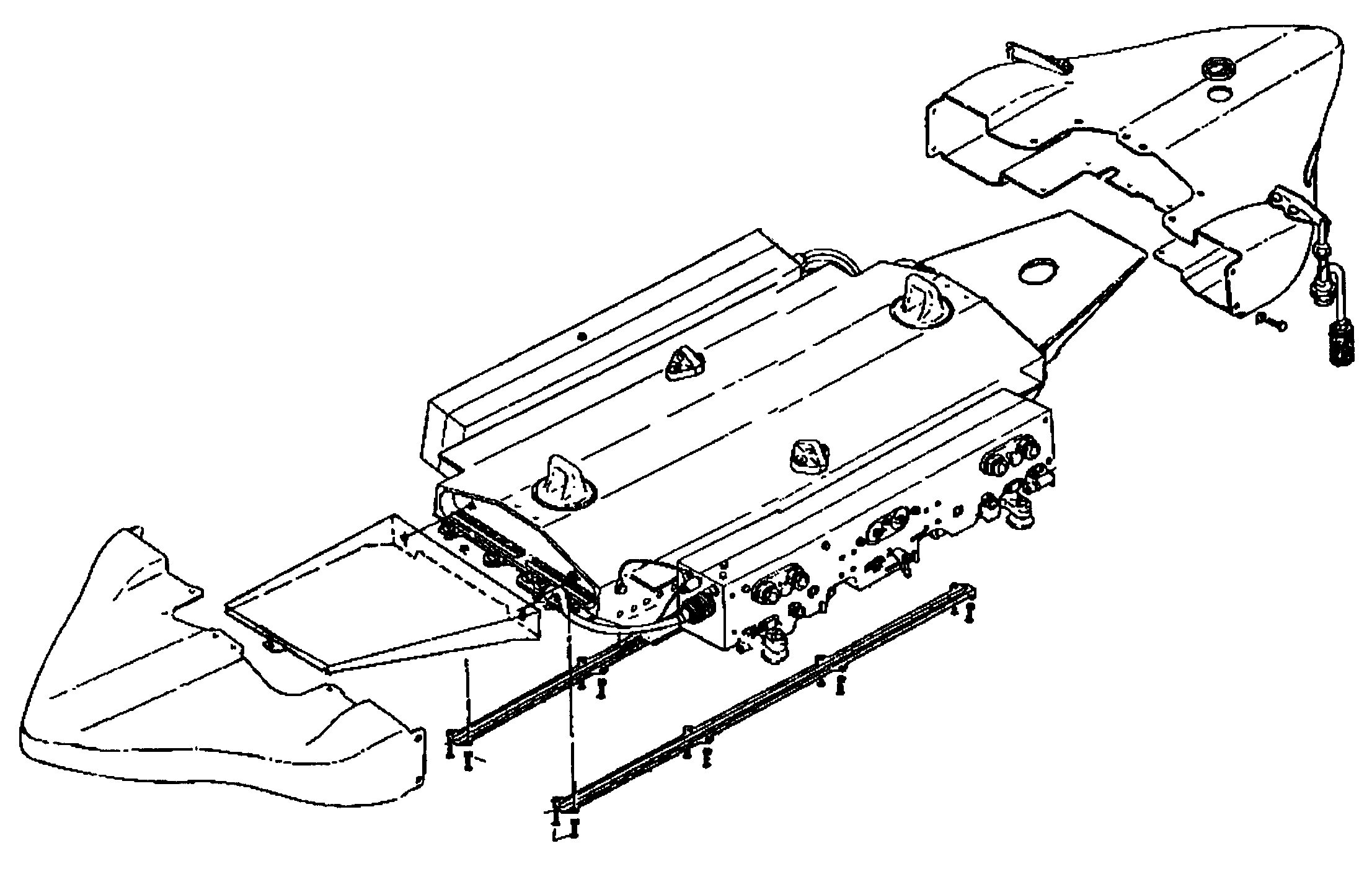
FIGURE 1. Notional Smart Rack
2. APPLICABLE DOCUMENTS
2.1 Government documents. The following documents of the exact issue shown form a part of this specification to the extent specified herein.
2.1.1 Specifications, and standards.
SPECIFICATIONS
MIL-PRF-5624F Turbine Fuel, Aviation Grades JP-4, JP-5 and JP-5/JP-8ST
MIL-PRF-7808L Lubricating Oil, Aircraft Turbine Engine, Synthetic Base
MIL-A-8591H Airborne Stores, Suspension Equipment and Aircraft – Store
Amend 1 Interface (Carriage Phase)
MIL-PRF-23699F Lubricating Oil, Aircraft Turbine Engine, Synthetic Base, NATO Code Number O-156
MIL-PRF-83282D Hydraulic Fluid, Fire Resistant, Synthetic Hydrocarbon Base, Metric,
Amend 1 NATO Code Number H-537
MIL-PRF-85570C Cleaning Compound, Aircraft Exterior
3036AS104 BRU-33A/A Bomb Rack
STANDARDS
MIL-STD-464 Electromagnetic Environmental Effects Requirements for Systems
MIL-STD-704A Aircraft Electric Power Characteristics
MIL-STD-1553B, Digital Time Division Command/Response Multiplex Data Bus
Notice 4
MIL-STD-1760B Aircraft / Store Electrical Interconnection System
2.1.2 Federal codes and Air Force regulations
U.S.C. 15 Toxic Substance Control Act
U.S.C. 42 Clean Air Act
DFAR 5352.247-9005 Shipping Container Bar Code Numbering
CFR 40 Protection of Environment, U.S. Environmental Protection Agency (EPA)
AFR 19-15 Reduction In Use of Chloroflorocarbons, Halons, and Other Substances that Deplete Stratospheric Ozone
2.1.3 Interface control documents. Latest version of document in effect.
BICD-1025-001 BRU-55 Smart Rack Interface Control Document *
ICD No. U0050039 Joint Standoff Weapon Interface Control Document
JICD 1515001 Joint Direct Attack Munitions Interface Control Document
WICD 1526001 Wind Corrected Munitions Dispenser Interface Control Document
* At the time this document was created it covered both the Navy and Air Force versions under the BRU-55 nomenclature. This document covers both the BRU-55/A and the BRU-57/A. This document will be referreed to as the Smart Rack ICD.
2.2 Non-Government documents. The following documents of the exact issue shown form a part of this specification to the extent specified herein.
SPECIFICATIONS
McDonnell Aircraft Company
PS 68-730134A 14 Inch Suspension Bomb Rack (BRU-46 Ejector Unit)
2.3 Order of precedence. In the event of conflict between the text of this specification and the references cited herein, the text of this specification takes precedence. Nothing in this specification, however, supersedes applicable laws and regulations unless a specific exemption has been obtained.
In the event of conflict between the requirements defined in this specification, the following order of precedence shall apply:
1. Safety 4. Maintainability
2. Performance 5. EMC
3. Reliability 6. Producibility
3. REQUIREMENTS
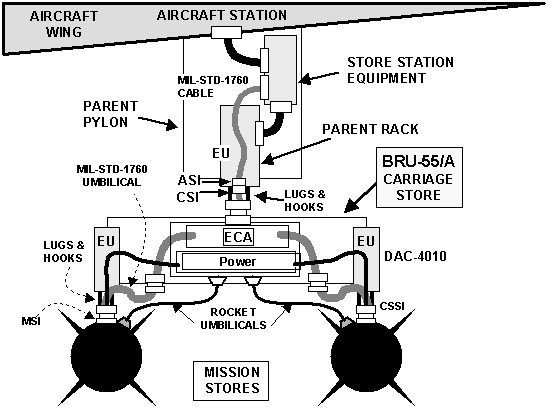
3.1 Item definition. The Smart Rack shall provide the capability for multiple carriage and employment of MIL-STD-1760 mission stores from a single aircraft station. A MIL-STD-1760 Class II Aircraft Station Interface (ASI) to Carriage Store Interface (CSI) shall be the only electrical interface between the aircraft and the Smart Rack. The modification to the baseline multiple bomb rack includes of new wiring harnesses, connectors and circuitry to control mission store and ejector unit functions and to communicate with the carriage aircraft. This modification is defined as the Smart Rack ECA. Refer to Figures 2 and 3 for general layout and connector interfaces for the two versions of the Smart Rack.

FIGURE 2. BRU-55/A General Layout and Connector Interfaces
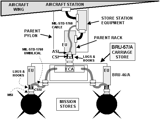
FIGURE 3. BRU-57/A General Layout and Connector Interfaces
3.1.1 General description. The Smart Rack shall consist of the following major elements.
a. A two store position multiple carriage rack strongback (support assembly):
c. One ECA.
d. Connector interfaces.
f. Tail fairing with provision for retention of the CSSI umbilical.
The term Smart Rack will be used when reference is made to the requirements that are common to both configurations. References to the VER in this specification mean the BRU-57/A configuration. References to the CVER in this specification mean the BRU-55/A configuration. The BRU-33A/A CVER is a two store position multiple carriage rack presently used on F/A-18 aircraft.
The ECA shall provide an electrical interconnection system for the transfer of power and digital data between the aircraft and mission stores through the carriage rack. The Smart Rack shall incorporate a fully functional MIL-STD-1760 Class II signal set at the CSI and at each CSSI. Umbilicals between the Smart Rack carriage store and the mission store shall incorporate a Class II signal set. This specification does not preclude the incorporation of fully functional MIL-STD-1760 Class I signal sets at the CSI, CSSI, and in the CSSI-MSI umbilical, but a Class I interface is not a requirement and is unnecessary for carriage of weapons specified in 3.2.1.1.
When connected to the ASI via the CSI, the Smart Rack shall be fully functional when provided (at the ASI) with the voltage and current levels as specified in MIL-STD-1760. The Smart Rack shall enable mission stores which meet the MSI requirements of MIL-STD-1760 to function properly when connected to either of the Smart Rack CSSI interfaces. The Smart Rack CSI shall function as a MSI when viewed from the ASI and the CSSI shall function as an ASI when viewed from the MSI. The Smart Rack shall include capabilities for communications between the aircraft and individual MIL-STD-1760 mission stores via the digital multiplex data (Mux) interface.
The BRU-55/A shall be capable of carrying, fuzing, and releasing the authorized stores specified for the existing BRU-33A/A CVER and in 3.2.1.1 herein.
3.1.2 Configuration difference descriptions.
3.1.4 Government furnished property.
3.1.4.12 For the BRU-55/A.
a. BRU-33A/A CVER, P/N 3036AS100 (old P/N JO14000-541).
3.1.4.21 For the BRU-57/A.
a. Strongback, P/N J014005-1, from the BRU-33/A VER.
3.1.5 Operational and organizational concepts. No unique or unusual operational concepts are required for the Smart Rack.
3.2 Characteristics.
3.2.1 Interface requirements.
a. JDAM JICD 1515001
b. JSOW ICD No. U0050039
c. WCMD WCID 1526001
3.2.1.2 Interface connectors signal set. The interface connector signal set and insert arrangements for the CSI and CSSI interfaces shall be in accordance with MIL-STD-1760. Detailed characteristics of the signal set and connectors are found in Section 4 of the BRU-55 Interface Control Document (ICD) (BICD-1025-001).
3.2.1.3 Smart Rack CSI general requirements. The Smart Rack shall provide a connection at the CSI in accordance with the requirements of MIL-STD-1760 Class II signal set. Unless otherwise specified herein, detailed electrical requirements for each of these signals at the CSI shall comply with MIL-STD-1760 requirements and the BRU-55 ICD (For exceptions see discussions of Status Word Response Time in paragraph 3.2.1.4.2.1(g), and Data Propagation Delay in paragraph 3.2.1.4.2.1(b)).
3.2.1.3.1 CSI power interfaces. The Smart Rack shall operate as specified when presented at the CSI with steady state voltages within the limits of Table 1, and shall not sink steady state current in excess of the values shown in the table.
The maximum transient load applied shall not exceed the maximum load current level of Figure (7) of MIL-STD-1760. The Smart Rack shall not be damaged and shall continue normal operation during transients as follows:
a. Voltage spikes that do not exceed +50% or -150% of the nominal direct current (DC) line voltage, nor +/- 50% for alternating current (AC) power lines for less than 50.0 microseconds duration (referenceMIL-STD-464).
b. Voltage transients within limit (2) of Figure (9), MIL-STD-704A.
The Smart Rack shall not be damaged during transients as defined by limits (1) and (4) of Figure (9), MIL-STD-704A, and shall resume normal operation when supply voltages return to within steady state limits.
TABLE 1. Power Requirements at the CSI
|
POWER REQUIREMENTS
|
||
|
INTERFACE LINE |
MAX. ALLOWED CURRENT |
VOLTAGE LEVEL |
|
28V DC Power 1 |
10A |
22.0V to 29.0V |
|
Power 1 Return |
10A |
0V |
|
28V DC Power 2 |
10A |
22.0V to 29.0V |
|
Power 2 Return |
10A |
0V |
|
115V AC, Phase A |
10A, 400 Hz |
108V rms to 118V rms |
|
115V AC, Phase B |
10A, 400 Hz |
108V rms to 118V rms |
|
115V AC, Phase C |
10A, 400 Hz |
108V rms to 118V rms |
|
115V NEUTRAL |
10A |
0V |
3.2.1.4 Smart Rack CSI detailed requirements.
3.2.1.4.1 CSI high bandwidth (HB) interface. The CSI shall provide connections for two (2) HB interfaces (HB1, HB3). Each HB interface shall include a signal connection and a signal return (shield). The Smart Rack shall be capable of switching the HB signals to each CSSI as a function of aircraft command. Detailed characteristics at the CSI HB interface shall be as defined in MIL-STD-1760 for the mission store HB interfaces.
3.2.1.4.2 CSI Mux interface. The Smart Rack shall provide connections for the aircraft station Mux interfaces (Mux A and Mux B) at the CSI for rack control and monitor, MIL-STD-1760 CSSI signal set control and monitor, and transfer of information to stores. Each of the Mux A and Mux B connections
shall include a data high, a data low and a shield connection. Detailed characteristics at the CSI Mux A and B interfaces shall be as defined in MIL-STD-1760 for mission store Mux A and B interfaces.
3.2.1.4.2.1 Mux interface functional characteristics.
a. The Smart Rack shall provide an active extension of the MIL-STD-1553 Mux interface between the ASI and MSI(s) as well as the Smart Rack remote terminal (RT).
d. Data uncertainty between the mission store and the aircraft through the Smart Rack shall not exceed 2 milliseconds (msec).
f. The Smart Rack shall respond to those messages whose command word terminal address corresponds to:
(1) the address encoded on the address interface monitored at the CSI; and
(2) the broadcast address.
g. The Smart Rack MIL-STD-1553 status word response time shall not exceed 14.4 microseconds (requirement). The goal is 12.0 microseconds.
3.2.1.4.3 CSI low bandwidth (LB) interface. The Smart Rack shall provide connections for a LB interface at the CSI for transferring LB signals in accordance with the requirements of MIL-STD-1760. The Smart Rack shall be capable of switching the LB signal to each CSSI as a function of aircraft command. Detailed characteristics at the CSI LB interface shall be as specified in MIL-STD-1760 for the mission store LB interface.
3.2.1.4.4 CSI release consent interface. The Smart Rack shall provide connections for a release consent interface at the CSI for transferring an enable and inhibit signal to the Smart Rack and the selected CSSI(s) as commanded by the aircraft. The release consent interface shall include a release consent signal connection referenced to the 28V DC power 2 return connection. Release consent, when in the enable state, shall indicate aircraft consent for the Smart Rack to perform safety-critical functions when commanded over the Mux interface. The release consent provided by the Smart Rack to the CSSIs shall be hardware interlocked with the aircraft release consent discrete provided at the CSI. Detailed electrical requirements for the CSI release consent signal shall be as defined in MIL-STD-1760 for the mission store release consent interface. The Smart Rack CSI release consent interface shall comply with the voltage spike requirements of 3.2.1.3.1.
3.2.1.4.5 CSI interlock interface. The Smart Rack shall provide interlock connections at the CSI for the aircraft to monitor the electrically mated status of the Smart Rack to the parent pylon. Detail requirements for the CSI interlock interface shall be as defined in MIL-STD-1760 for the mission store interlock interface.
3.2.1.4.6 CSI address interface. The Smart Rack shall provide address connections at the CSI for the aircraft to set the address of the Smart Rack’s internal remote terminal (RT). Detail requirements for the CSI address interface shall be as defined in MIL-STD-1760 for the mission store address interface.
3.2.1.4.7 CSI structure ground interface. The Smart Rack shall provide a connection at the CSI which is terminated to structure ground and capable of carrying 10 amperes (A) (continuous). The structure ground interface shall not be used as a signal return or power return path. The structure ground interface shall be as defined in MIL-STD-1760 for the mission store structure ground interface.
3.2.1.4.8 CSI 28V DC power 1 and power 2 interfaces. The Smart Rack shall provide connections for the 28V DC power 1 and power 2 interface at the CSI. The CSI shall contain 28V DC power 1 and power 1 return connection and 28V DC power 2 and power 2 return connections. If any 28V DC power interface is not utilized, the impedance between the power connection and the associated return connection at the CSI shall be greater than 100 kilohms (kW ) (at DC). Detailed electrical requirements for the CSI 28V DC power #1 and #2 interfaces shall be as defined in MIL-STD-1760 for mission store 28V DC power #1 and #2.
3.2.1.4.8.1 Voltage level. The Smart Rack shall be compatible with the voltages defined in MIL-STD-1760 for the aircraft 28V DC power interface. The Smart Rack shall comply with the voltage spike requirements of 3.2.1.3.1 at the CSI.
3.2.1.4.9 CSI 115/200 Volts (V) AC power interface. The Smart Rack shall provide connections for the 115/200V AC power interface at the CSI. The CSI shall contain 115V AC phase A, phase B, phase C and neutral connections. If any 115V AC phase is not used, the impedance between the phase connection and the associated neutral connection at the CSI shall be greater than 100 kW (at 400 Hertz (Hz)). Detailed electrical requirements for the CSI 115/200 V AC power interfaces shall be as defined in MIL-STD-1760 for mission store 115/200 V AC power.
3.2.1.4.9.1 Voltage level. The Smart Rack shall be compatible with voltage defined in MIL-STD-1760 for the aircraft 115/200V AC power interface. The Smart Rack shall comply with the voltage spike requirements of 3.2.1.3.12 at the CSI.
3.2.1.4.9.2 Power interruption. Power interrupts of 200 microseconds (m sec) or less shall have no effect on the Smart Rack function. Full function, including communication, shall be maintained during such interrupts and no power interrupt notification shall occur. For power interrupts greater than 200 m sec, the Smart Rack may request full or partial initialization.
3.2.1.4.10 CSI initialization. Detailed requirements for the CSI initialization shall be as defined in MIL-STD-1760 for store initialization.
3.2.1.4.11 CSI connector characteristics. The CSI connector characteristics shall be in accordance with 3.2.1.2 herein.
3.2.1.4.11.1 Connector receptacle. The CSI connector shall be a receptacle with socket contacts.
3.2.1.4.11.2 Connector location. The Smart Rack shall provide a single CSI electrical connector. The connector location shall be designed to allow the CSI connector to be placed at the locations specified in Section 6.1.3.1 of BRU-55 Smart Rack ICD. CSI connector location shall be reconfigurable by Organizational or Intermediate maintenance personnel. The keyway shall be oriented as defined in MIL-STD-1760.
3.2.1.5 Smart Rack CSSI general requirements. The Smart Rack shall provide two (2) CSSIs. The Smart Rack shall provide connections at the CSSI in accordance with the requirements of MIL-STD-1760 Class II signal set. Detailed electrical requirements for each of these signals at the CSSI shall comply with MIL-STD-1760 requirements and the BRU-55 ICD to electrically function with the MSI as specified herein. The Smart Rack shall not activate any power signals or discretes at the CSSIs unless commanded by the aircraft.
3.2.1.6 Smart Rack CSSI detailed requirements.
3.2.1.6.1 CSSI HB interface. The Smart Rack shall provide connections for two (2) HB interfaces (HB1, HB3) at each CSSI. Each HB interface shall include a signal connection and a signal return (shield) connection. The Smart Rack shall be capable of switching the HB signals to the CSSI(s) as a function of aircraft command. Detailed requirements for the CSSI HB interface shall be as defined in MIL-STD-1760 for the aircraft HB interfaces.
3.2.1.6.2 CSSI Mux interface. The Smart Rack shall provide two (2) Mux interface connections for the mission store data interface (Mux A and Mux B) at each CSSI for transferring information, store control and store status between the aircraft and a MIL-STD-1760 mission store. The Smart Rack shall provide an active extension of the Aircraft Mux interface for a Mux link between the aircraft and the mission stores. Detailed requirements for the CSSI Mux A and B interfaces shall be as defined in MIL-STD-1760 for the aircraft Mux A and B interfaces.
3.2.1.6.3 CSSI LB interface. The Smart Rack shall provide a connection for the LB interface at each CSSI. The Smart Rack shall be capable of switching the LB signal to the CSSIs as a function of aircraft command. Detail requirements for the CSSI LB interface shall be as defined in MIL-STD-1760 for the aircraft low bandwidth interface.
3.2.1.6.4 CSSI release consent interface. The Smart Rack shall provide connections for a release consent interface at each CSSI for transferring an enable and inhibit signal to the selected mission store. The release consent interface shall include a release consent signal connection referenced to the 28V DC power 2 return connection. Release consent, when in the enable state, shall indicate aircraft consent for stores to perform safety-critical functions when commanded over the Mux interface. The release consent provided by the Smart Rack to the CSSIs shall be interlocked with the aircraft release consent discrete provided at the CSI. Detail requirements for the CSSI release consent interface shall be as defined in MIL-STD-1760 for the aircraft release consent interface.
3.2.1.6.5 CSSI interlock interface. The Smart Rack shall provide an interlock interface at each CSSI for monitoring the mated status of the mission store connectors. Detail requirements for the CSSI interlock interface shall be as defined in MIL-STD-1760 for the aircraft interlock interface.
3.2.1.6.6 CSSI address interface. The Smart Rack shall provide a means for the host aircraft to assign a unique Mux address to the RT in the mission store mated to each CSSI. Detailed requirements for the CSSI address interface shall be as defined in MIL-STD-1760 for the aircraft address interface.
3.2.1.6.7 CSSI structure ground interface. The Smart Rack shall provide a connection in each CSSI which is terminated to its structure ground and capable of carrying 10A (continuous). The structure ground interface shall not be used as a signal return or power return path. The structure ground interface shall be as defined in MIL-STD-1760 for the aircraft structure ground interface.
3.2.1.6.8 CSSI 28V DC power 1 and power 2 interfaces. The Smart Rack shall provide the 28V DC power 1, power 1 return, and 28V DC power 2, power 2 return at each CSSI. Subject to the conditions of 3.2.1.6.8.1 through 3.2.1.6.8.4, CSSI 28V DC power #1 and #2 interfaces shall be as defined in MIL-STD-1760 for aircraft 28V DC power #1 and #2.
3.2.1.6.8.1 CSSI 28V DC power 1 interface. When commanded by the aircraft the Smart Rack shall distribute and control 28V DC power 1 to each CSSI. The Smart Rack shall be capable of distributing and controlling 28V DC power 1 maximum of 10A (continuous) at each CSSI simultaneously.
3.2.1.6.8.2 CSSI 28V DC power 2 interface. When commanded by the aircraft, the Smart Rack shall distribute and control 28V DC power 2 to each CSSI. The Smart Rack shall be capable of distributing and controlling 28V DC power 2 to each CSSI with a combined maximum of 10A (continuous) at both CSSIs.
3.2.1.6.8.3 Transfer requirements. The Smart Rack, when commanded by the aircraft, shall be capable of sourcing and independently controlling each 28V DC power interface through each CSSI.
3.2.1.6.8.4 Electrical characteristics. The voltage supplied to the MSI shall be as defined in MIL-STD-1760 for the mission store 28V DC power interface.
3.2.1.6.9 CSSI 115/200V AC power interface. The Smart Rack, when commanded by the aircraft, shall provide 115/200V AC power interface at each CSSI. The CSSI shall contain 115V AC Phase A, Phase B, Phase C, and neutral connections. The Smart Rack shall distribute and control the 115/200V AC power individually to each CSSI, as commanded by the aircraft. Subject to the conditions of 3.2.1.6.9.1 and 3.2.1.6.9.2, the CSSI 115/200 V AC power interfaces shall be as defined in MIL-STD-1760 for aircraft 115/200V AC power.
3.2.1.6.9.1 Transfer requirements. The Smart Rack, when commanded by the aircraft, shall be capable of independently controlling the 115/200V AC power interface through each CSSI.
3.2.1.6.9.2 Electrical characteristics.
3 2.1.6.9.2.1 Voltage level. The voltage supplied to the MSI shall be as defined in MIL-STD-1760 for the mission store 115/200V AC power interface.
3.2.1.6.9.2.2 Current loading. The Smart Rack when generating 28V DC for simultaneous delivery of 10A of 28V DC #1 to each CSSI shall be capable of distributing a combined total of 7.5 amps root-mean-square (rms) per phase to both CSSI 115/200V AC interfaces.
3.2.1.6.9.2.3 Power interruption. The Smart Rack shall be compatible with stores which require re-initialization following 115/200V AC power interrupts in excess of 200 m sec.
3.2.1.6.10 CSSI connector characteristics. The CSSI connector shall be a receptacle with socket contacts.
3.2.2 ECA functional and electrical characteristics. The ECA of the Smart Rack shall be capable of performing all functions required for carriage and release stores as described in paragraph 3.2.21.1.
3.2.2.1 Function requirements. The Smart Rack shall comply with message formatting, data encoding, information transfer rules and timing as described in MIL-STD-1760, Appendix B, and in Sections 3 and 5 of the BRU-55 Smart Rack ICD . The Smart Rack shall perform, but not be limited to the following functions to control the existing rack functions and MIL-STD-1760 compatible mission stores:
a. Provide for the control and monitor of all existing mission store ejector rack functions, as in Table 2, under aircraft command via Mux interface.
d. Provide for the control and switching of the HB and LB signals between aircraft and mission stores under aircraft command.
e. Monitor the status of the Smart Rack discretes.
f. Monitor all Mux interface inputs from the aircraft and perform appropriate functions as commanded by the aircraft.
g. Perform release of the mission stores based on the aircraft command. The Smart Rack ECA shall be capable of store-to-store minimum release interval of 10 milliseconds (msec).
h. Provide the control and distribution of the release consent discrete under aircraft command to MIL-STD-1760 compatible mission stores which require release consent discrete.
i. The Smart Rack ECA shall be capable of detecting errors in aircraft-to-Smart Rack terminal communications across the Mux interface. In the event that an error is detected, the Smart Rack shall inhibit the execution of any safety critical function as defined in Table B-XXII of MIL-STD-1760 Appendix B, and upon request from the aircraft, shall report the error to the aircraft.
j. The Smart Rack ECA shall be capable of providing the Smart Rack description message in response to an aircraft transmitted subaddress 0001 command to the Smart Rack.
TABLE 2. Ejector Unit Functions
|
Function |
DAC 4010 |
BRU-46/A |
|
Structure Ground |
J |
U |
|
+ 28V DC |
h |
--- |
|
+ 28V DC Return |
j |
--- |
|
Nose (#1) Arm |
D |
M |
|
Nose (#1) Arm Return |
W |
N |
|
Tail (#2) Arm |
d |
Z |
|
Tail (#2) Arm Return |
P |
a |
|
Center Arm |
--- |
c |
|
Center Arm Return |
--- |
b |
|
Store Sense |
X |
--- |
|
Store Sense Return |
G |
--- |
|
IFOBRL Lock |
E |
--- |
|
IFOBRL Lock Return |
C |
--- |
|
IFOBRL Lock Monitor |
b |
--- |
|
IFOBRL Unlock |
N |
--- |
|
IFOBRL Unlock Return |
B |
--- |
|
IFOBRL Unlock Monitor |
F |
--- |
|
Fire Line One Aft |
H |
R |
|
Fire Line One Return |
Z |
--- |
|
Fire Line Two Forward |
K |
B |
|
Fire Line Two Return |
a |
--- |
|
EBF High |
B |
--- |
|
EBF Return |
C |
--- |
|
Primary Stray Voltage Test |
--- |
S |
|
Secondary Stray Voltage Test |
--- |
T |
|
Hook Status Common |
--- |
D |
|
Hook Status Open |
--- |
E |
|
Hook Status Closed |
--- |
V |
3.2.2.2 Embedded controller resources. The embedded controller resources of the Smart Rack shall utilize a contractor-specified microprocessor and contractor designed controller firmware. Smart Rack processor shall have the following characteristics.
3.2.2.2.1 Processor. The reserve throughput and memory shall be 50 percent (%) of the initial requirements for throughput and memory usage as measured using the baseline production design. Any subsequent versions of the smart Rack design may have less than the 50% reserve margins.
3.2.2.2.2 Firmware. The Smart Rack is a hardware intensive application and the firmware shall not be changed in the field. The Smart Rack firmware shall not include any aircraft or weapon specific coding. The Smart Rack shall be free from defects associated with the year 2000 (Y2K defects) and shall operate satisfactorily before, during, and after the year 2000.
3.2.2.2.2.1 Firmware language. The Smart Rack firmware shall be developed using a commercially available compiler appropriate for the embedded CPU design. Since the Smart Rack is hardware intensive, the requirement for the use of Ada programming language is not applicable. The firmware shall be developed using a High Order (HO) computer language. Firmware shall be developed using standard software engineering practices to produce modular, structured and well-documented source code. The compiler chosen for the Smart Rack firmware should produce efficient target microprocessor code.
3.2.2.3 Bus coupling.
3.2.2
.3.1 Bus coupling of Smart Rack. The Smart Rack shall be transformer coupled to the aircraft weapons bus.3.2.2.3.2 Bus coupling of mission stores. The Smart Rack shall provide a transformer coupled stub at each CSSI. A fault on a mission store stub or RT shall not degrade the operation of the other mission store or the Smart Rack.
3.2.2.4 ECA power supply.
3.2.2.4.1 28V DC 1 ECA power supply. The Smart Rack shall be capable of simultaneously providing 10A DC continuously to each CSSI. This power shall be derived from the 115/200V AC three phase CSI power. The power supply efficiency at full load shall exceed 80%.
3.2.2.4.2 EBF power supply. The BRU-55/A shall be capable of supplying EBF voltages of + 300V DC, + 195V DC and ground as commanded by the aircraft. The voltages shall be required to within + 10% of nominal and capable of supplying up to 100 watts total to EUs. The power supply efficiency when fully loaded shall exceed 80%.
3.2.3 Physical characteristics.
3.2.3.1 Mass properties. The mass properties of the BRU-55/A and BRU-57/A shall be within the limits defined in Table 3.
|
Property |
BRU-55/A |
BRU-57/A |
|
Weight, lbf |
193.0 +/- 10% |
247.1 +/- 10% |
|
Pitch Moment of Inertia, Slug-ft2 |
5.62 +/- 10% |
8.91 +/- 10% |
|
Yaw Moment of Inertia, Slug-ft2 |
8.27 +/- 10% |
12.42 +/- 10% |
|
Roll Moment of Inertia, Slug-ft2 |
3.30 +/- 10% |
3.95 +/- 10% |
|
Center-of-Gravity Location, inches aft of forward mounting lug |
15.5 +/- 0.5 |
15.5 +/- 0.5 |
3.2.3.2 Aerodynamic drag. The design shall maintain minimum free-body aerodynamic drag of the Smart Rack. For the Smart Rack, contractor changes to the CVER configuration shall be such that wind tunnel testing shall not be required.
3.2.3.3 Umbilical retention. A means to secure and retain the Smart Rack to mission store umbilical(s), in a ready for issue condition, shall be provided to ensure that the umbilical remains with the Smart Rack once the mission store is released. The location of the retention device should be positioned to minimize or negate degrading the flow field effects on the mission store to retain current mission store separation characteristics. The retaining device shall be located such that the maximum pull separation forces on the connector(s) shall be 90 pounds (lbs) (400 Newtons) for a straight pull (0o) and 100 lbs (445 Newtons) for a 15° pull and shall not exceed 100 lbs for any angle between 0o and 15o.
3.2.3.4 Modification constraints.
3.2.3.4.1 BRU-55/A. Changes to the mechanical interface (i.e. suspension lugs, hoist clevises, sway brace contact points, ejector unit hooks and sway brace assemblies) and physical shape, except for the incorporation of the MIL-STD-1760 connector, a second lower cable channel and the umbilical retention device(s), shall not be permitted. Changes to the baseline EU configuration, shape, orientation, location or functionality shall not be permitted.
3.2.3.4.2 BRU-57/A. Changes to the physical shape of the baseline VER shall be minimized. The BRU-46/A EUs shall be integrated onto the VER strongback, maintaining the store carriage positions and attitudes of the baseline CVER configuration. Changes to the BRU-46/A EU configuration, shape or functionality shall not be permitted.
3.2.3.5 Service and test access. The Smart Rack modifications shall not restrict access to service or test areas currently accessible on the baseline CVER/VER with either mission stores loaded or unloaded. Service and test access to a BRU-46/A mounted on the BRU-57/A shall not be less than when it is mounted directly on an aircraft.
3.2.3.6 Design strength. The Smart Rack shall have the strength and rigidity to support the forces and moments resulting from the loading conditions as specified in section 3.2.6. Sufficient strength shall be provided over the Smart Rack service life. The maximum loads expected in normal operational deployment are designated herein as limit loads.
3.2.3.6.1 Yield Loads. The structure shall have positive margin of safety with respects to the yield loads. Yield loads are obtained by multiplying the limit loads by 1.15. The effects of deformation remaining after application and removal of the yield loads shall not affect form, fit, or function of the Smart Rack.
3.2.3.6.2 Ultimate Loads. The structure shall have positive margin of safety with respects to the ultimate loads. Ultimate loads are obtained by multiplying the limit loads by 1.5. The Smart Rack shall not fail catastrophically during the application of the ultimate loads. Catastrophic failure is defined as a failure that results in damage to the aircraft and/or inadvertent release of a store.
3.2.4 Reliability. The Smart Rack reliability requirements shall be allocated to all new components and modified CVER/VER equipment. New and modified CVER/VER components shall not degrade the reliability of the unmodified government provided components.
3.2.4.1 Component reliability. The Smart Rack, less the CSSI to MSI umbilicals, shall have a Mean Time Between Failure (MTBF) not less than 3200 hours (hrs). The CSSI-to-MSI umbilicals shall withstand without damage or loss of function a minimum of 100 store ejections (per MIL-C-38999) or 3200 hrs of operation, whichever comes first.
3.2.4.2 Mission reliability. The mission reliability of the Smart Rack for successful execution of arm and release on command shall be a minimum of 0.995, based on occurrences of attempted arm and release commands.
3.2.4.3 Safety reliability. The Smart Rack resistance to inadvertent arm and release of stores shall be a minimum of 0.9999 per mission.
3.2.5 Maintainability. The Smart Rack ECA shall feature modular construction and testability, BIT circuitry and sufficient test points to meet the maintainability requirements. The Smart Rack shall have an organizational level (O-level) Mean Time To Repair (MTTR) of less than or equal to 45 minutes (min) and a maximum corrective maintenance time of one hour (hr) at the 95th percentile. Incorporation of the ECA and other modifications to the CVER/VER shall not impact the maintainability of those elements/components retained on the baseline CVER/VER.
3.2.5.1 Maintainability design. The electronic system shall be designed to provide functional and physical partitioning of all levels of assembly to enable modular packaging of assemblies and subassemblies into shop replaceable assemblies (SRA).
3.2.5.2 Shop replaceable assembly. Each SRA shall be designed and constructed for removal and replacement as a modular package. To the maximum extent practicable, each SRA shall be designed into discrete functional packages for discard at failure rather than repair. Physical measures shall be provided (e.g., alignment pins, keying, etc.) to preclude interchange of SRAs of similar form which are not functionally interchangeable and to preclude improper mounting at installation. Smart Rack installation hardware that must be removed to replace SRAs shall have captive fasteners.
All SRAs shall be common between the BRU-57/A and BRU-55/A except for the EBF power supply.
3.2.5.4 Peculiar support equipment (PSE). The Smart Rack shall minimize the requirements for PSE. Adapters and interconnecting devices needed to adapt the Smart Rack to test equipment or common support equipment shall be simple in design and permit commonality of Unit-Under-Test application. Minimum modifications to the Preload Armament Circuits Test Set (SERD 75060, P/N 16U75060-835 USAF) and the Stores Release Equipment Test Set (SERD 75500, P/N 16U75500-855 USAF) will be required to make them compatible with the Smart Rack.
3.2.5.5 Organizational (O-level) maintenance. The Smart Rack ECA shall be designed such that the O-level MTTR shall not exceed 45 minutes. The Smart Rack shall be designed such that testing can be accomplished using Built in Test (BIT), and any MIL-STD-1760 compliant test equipment. BIT used in conjunction with O-level support equipment shall fault isolate to the defective weapon replaceable assembly (WRA) for 100% of faults. The Smart Rack shall not require any scheduled maintenance other than maintenance prescribed for the existing CVER.
NOTE: Throughout this specification, any references to O-level maintenance (including O-level personnel and equipment) shall imply on-equipment O-level maintenance in the case of the BRU-57/A.
3.2.5.6 Intermediate (I-level) maintenance. The Smart Rack shall be designed such that the I-level MTTR shall not exceed 1.0 hrs. Maintenance of the ejector units and other government furnished equipment shall be in accordance with the applicable specification (3036AS104 for P/N J014005-1, P/N 3036AS100 and P/N 3036AS400, and PS 68-730134A for P/N 116200-8) and is not included in the MTTR. Time to remove and replace the ejector racks is included in the MTTR. The Smart Rack shall be designed such that testing can be accomplished using any MIL-STD-1760 compliant test equipment.
NOTE: Throughout this specification, any references to I-level maintenance (including I-level personnel and equipment) shall imply off-equipment O-level maintenance in the case of the BRU-57/A.
3.2.5.6.1 Smart Rack fault isolation level. The Smart Rack shall be designed such that, when tested by I-level maintenance equipment, the fault isolation performance shall be as listed in Table 4.
TABLE 4. Non-Ambiguous SRA Isolation Groups
|
% of WRA fault isolated |
SRA ambiguity group size |
|
100% |
no greater than 3 SRAs |
|
95% |
no greater than 2 SRAs |
|
90% |
no greater than 1 SRA |
3.2.5.7 Built-in-test. The Smart Rack shall be capable of autonomously testing its operational readiness and reporting the results of these tests via the Mux interface. BIT shall consist of Power-On Self Test, Periodic BIT, and Initiated BIT as described below. The Smart Rack shall be capable of performing all varieties of BIT without the aid of external support equipment.
3.2.5.7.1 Power on self test (POST). POST shall execute automatically upon application of power to the Smart Rack. POST shall verify that the ejector units and the MIL-STD-1760 outputs to the mission stores are in a safe state. POST shall test the proper functioning of as much of the ECA as is possible without energizing any output signals to the mission stores or the ejector units.
3.2.5.7.2 Periodic built-in-test (PBIT). PBIT shall execute continuously as a background task whenever the Smart Rack is functioning. PBIT shall test the proper functioning of as much of the ECA as is possible without altering the state of any output signals to the mission stores or ejector units or otherwise interfering with the normal operation of the Smart Rack.
3.2.5.7.3 Initiated built-in-test (IBIT). IBIT shall execute upon command from the aircraft over the Mux interface. IBIT shall test the proper functioning of as much of the ECA and ejector units as is possible under the prevailing operating conditions in both mission and maintenance environments without compromising safety. If mission stores are present, IBIT shall not change the state of any output signals to the mission stores. IBIT shall not permit firing voltage to be sent to an EU.
3.2.5.7.4 Fault detection and isolation. Any failure of the Smart Rack to function properly that is detected during any type of BIT shall result in an advisory or caution being available for transmission to the aircraft over the Mux interface. BIT shall be able to isolate detected faults and make this data available for transmission to the aircraft over the Mux interface.
3.2.5.7.4.1 BIT fault detection level. The combination of PBIT and IBIT with I-level support equipment shall be capable of detecting 98% of all possible faults within the ECA.
3.2.5.7.4.2 BIT fault isolation level. The combination of PBIT and IBIT with I-level support equipment shall be capable of isolating faults to the degree specified in Table 5.
TABLE 5. BIT Fault Isolation Level.
|
Percentage of Faults Detected |
Degree of Isolation |
|
100% |
no greater than 6 SRAs |
|
95% |
no greater than 5 SRAs |
|
90% |
no greater than 4 SRAs |
|
85% |
no greater than 3 SRAs |
|
80% |
no greater than 2 SRAs |
|
75% |
no greater than 1 SRA |
3.2.5.7.5 Design growth limits. The growth of the ECA design due to the incorporation of BIT circuitry and devices shall not exceed 10% of the ECA parts and devices.
3.2.5.7.6 False alarm rate. The probability of false indications of Smart Rack failures shall not exceed 1% of all BIT indicated failures.
3.2.5.7.7 Fail-safe provisions. The circuits and devices which provide BIT shall be designed so that failure of these circuits or devices will not induce any other failures or functions.
3.2.5.7.8 Calibration. The BIT circuitry shall be designed such that no calibration is required.
3.2.6 Environmental conditions. The Smart Rack shall not be damaged and shall operate within the required performance levels as defined in this specification after exposure to any logical combination of the maintenance, transportation, and storage environmental conditions specified in the following subparagraphs. The Smart Rack shall operate without damage within the required performance levels during and after exposure to any logical combination of the captive carriage environmental conditions specified in the following subparagraphs. Damage shall be defined as any degradation in performance levels defined in this specification due to breakage, misalignment, loosening, detachment, locking, humidity intrusion, or material degradation.
3.2.6.1 Temperature.
3.2.6.1.1 Maintenance, transportation, and storage.
3.2.6.1.1.1 High tTemperature. The Smart Rack shall operate satisfactorily after exposure to the maximum air temperature at the cyclic levels of Table 6 for 168 hours (seven cycles).
TABLE 6. Induced, High Temperature Storage Cycle
|
Time of Day (hr) |
Temperature ° F (° C) |
Time of Day (hr) |
Temperature ° F (° C) |
|
0100 0200 0300 0400 0500 0600 0700 0800 0900 1000 1100 1200 |
95 (35) 94 (34) 94 (34) 92 (33) 92 (33) 91 (33) 97 (36) 104 (40) 111 (44) 124 (51) 133 (56) 145 (63) |
1300 1400 1500 1600 1700 1800 1900 2000 2100 2200 2300 2400 |
156 (69) 158 (70) 160 (71) 158 (70) 153 (67) 145 (63) 131 (55) 118 (48) 105 (41) 103 (39) 99 (37) 95 (35) |
3.2.6.1.1.2 Low temperature. The Smart Rack shall operate satisfactorily after exposure to a minimum temperature of -54° C (-65° F) for 24 hours.
3.2.6.1.2 Captive carriage.
3.2.6.1.2.1 High temperature. The Smart Rack shall operate satisfactorily during and after exposure to a high temperature environment of 93° C (200° F) for 1 hour.
3.2.6.1.2.2 Low temperature. The Smart Rack shall operate satisfactorily during and after exposure to a low temperature environment of -54° C (-65° F) for 2 hours.
3.2.6.1.2.3 Temperature shock. The Smart Rack shall operate satisfactorily during and after exposure to a sudden (less than 5 minutes) atmospheric temperature change over the range from -54° C (-65° F) to 93° C (200° F). A minimum of three cycles shall be required.
3.2.6.2 Humidity.
3.2.6.2.1 Maintenance, transportation, and storage. The Smart Rack shall operate satisfactorily after exposure to seven temperature/humidity cycles as defined in Table 7.
TABLE 7. Induced, Hot-Humid Humidity Cycle.
|
Time of Day (hr) |
Temperature ° F (° C) |
Relative Humidity (%) |
|
0100 0200 0300 0400 0500 0600 0700 0800 0900 1000 1100 1200 1300 1400 1500 1600 1700 1800 1900 2000 2100 2200 2300 2400 |
95 (35) 94 (34) 94 (34) 93 (34) 92 (33) 91 (33) 97 (36) 104 (40) 111 (44) 124 (51) 135 (57) 144 (62) 151 (66) 156 (69) 160 (71) 156 (69) 151 (66) 145 (63) 136 (58) 122 (50) 105 (41) 103 (39) 99 (37) 95 (35) |
67 72 75 77 79 80 70 54 42 31 24 17 16 15 14 16 18 21 29 41 53 58 62 63 |
3.2.6.2.2 Captive carriage. The Smart Rack shall operate satisfactorily during and after seven Humidity/Temperature/Altitude cycles as defined in Figure 4 without interruption of a cycle.
3.2.6.3 Altitude.
3.2.6.3.1 Maintenance, transportation, and storage. The Smart Rack shall operate satisfactorily after exposure to pressure altitudes from 280 feet below mean sea level to 12,000 feet above mean sea level.
3.2.6.3.2 Captive carriage. The Smart Rack shall operate satisfactorily during and after exposure to pressure altitudes from mean seal level to 50,000 feet above mean sea level.

FIGURE 4. Temperature/Humidity/Altitude Cycling
3.2.6.4 Vibration.
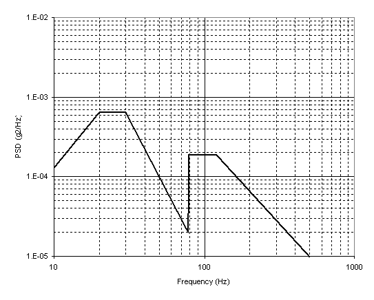
3.2.6.4.1 Maintenance, transportation, and storage. The Smart Rack shall operate satisfactorily after exposure to the transportation vibration levels as defined in Figures 5 (a through c) for four hours in each axis.
3.2.6.4.2 Captive carriage. The Smart Rack shall operate satisfactorily during and after exposure to the vibration levels associated with captive flight on the F-16 and F/A-18 aircraft.
3.2.6.4.2.1 BRU-55/A. The BRU-55/A vibration environment on the F/A-18 is defined in Figure 6 (a through f). The levels are defined for the center of the parent carriage rack. The levels shall be applied for a duration of 120 minutes for each level in each axis.
3.2.6.4.2.21 BRU-57/A. The BRU-57/A vibration environment on the F-16 is defined in Figure 76 (a through i). The levels are defined for the strongback near the forward and aft electronic tray support points. The levels shall be applied for 81 minutes for the loaded levels, 162 minutes for the unloaded levels, and 21 minutes for the unloaded buffet levels in each axis.
3.2.6.4.2.2 BRU-55/A. The BRU-55/A vibration environment on the F/A-18 is defined in Figure 7 (a through f). The levels are defined for the center of the
parent carriage rack. The levels shall be applied for a duration of 120 minutes for each level in each axis.
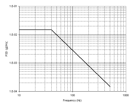
1.04 GRMS
|
Freq (Hz) |
PSD (g2/Hz) |
|
10 40 500 |
0.01500 0.01500 0.00015 |
FIGURE 5(a). Transportation Vibration, Vertical Axis
0.20 GRMS
|
Freq (Hz) |
PSD (g2/Hz) |
|
10 20 30 78 79 120 500 |
0.00013 0.00065 0.00065 0.00002 0.00019 0.00019 0.00001 |
FIGURE 5(b). Transportation Vibration, Lateral Axis
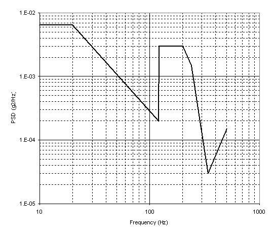
0.74 GRMS
|
Freq (Hz) |
PSD (g2/Hz) |
|
10 20 120 121 200 240 340 500 |
0.00650 0.00650 0.00020 0.00300 0.00300 0.00150 0.00003 0.00015 |
FIGURE 5(c). Transportation Vibration, Longitudinal Axis
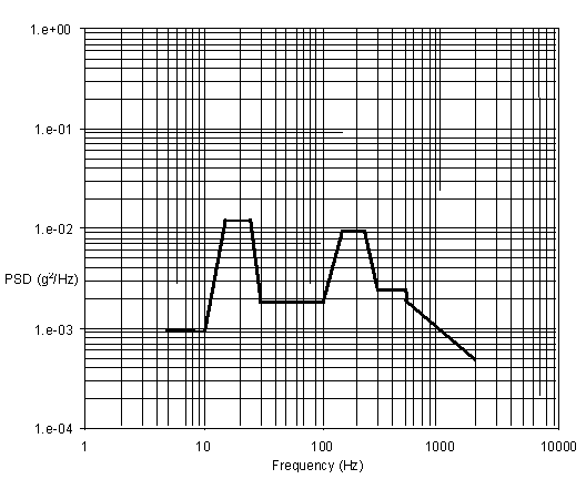
1.85 GRMS
|
Freq (Hz) |
PSD (g2/Hz) |
Freq (Hz) |
PSD (g2/Hz) |
|
5 |
9.40e-04 |
150 |
9.50e-03 |
|
10 |
9.40e-04 |
225 |
9.50e-03 |
|
15 |
1.20e-02 |
300 |
2.40e-03 |
|
25 |
1.20e-02 |
500 |
2.40e-03 |
|
30 |
1.80e-03 |
520 |
1.90e-03 |
|
100 |
1.80e-03 |
2000 |
4.80e-04 |
FIGURE 6(a). F/A-18 Non-Buffet Vertical
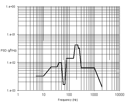
3.63 GRMS
|
Freq (Hz) |
PSD (g2/Hz) |
Freq (Hz) |
PSD (g2/Hz) |
|
5 |
3.20e-03 |
150 |
1.40e-02 |
|
10 |
3.20e-03 |
175 |
4.20e-02 |
|
20 |
7.00e-03 |
225 |
4.20e-02 |
|
35 |
7.00e-03 |
235 |
3.20e-02 |
|
40 |
9.70e-03 |
250 |
3.20e-02 |
|
50 |
9.70e-03 |
300 |
6.40e-03 |
|
60 |
1.60e-03 |
1000 |
6.40e-03 |
|
70 |
1.60e-03 |
2000 |
1.30e-03 |
|
80 |
1.40e-02 |
FIGURE 6(b). F/A-18 Non-Buffet Lateral
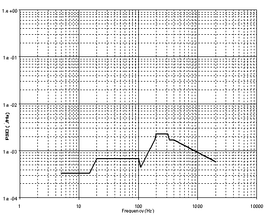
1.41 GRMS
|
Freq (Hz) |
PSD (g2/Hz) |
Freq (Hz) |
PSD (g2/Hz) |
|
5 |
3.40e-04 |
200 |
2.30e-03 |
|
15 |
3.40e-04 |
315 |
2.30e-03 |
|
20 |
6.90e-04 |
330 |
1.80e-03 |
|
100 |
6.90e-04 |
335 |
1.70e-03 |
|
110 |
4.50e-04 |
400 |
1.70e-03 |
|
190 |
1.75e-03 |
2000 |
5.90e-04 |
|
195 |
2.00e-03 |
FIGURE 6(c). F/A-18 Non-Buffet Longitudinal
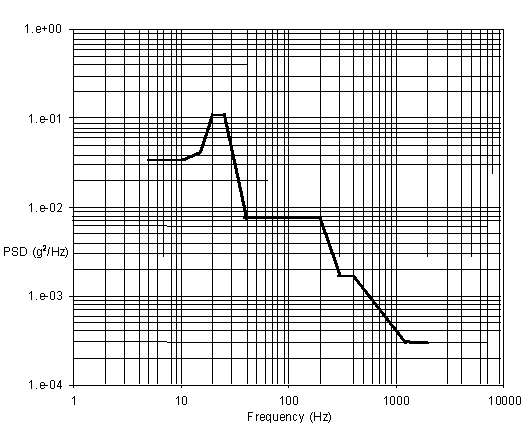
2.07 GRMS
|
Freq (Hz) |
PSD (g2/Hz) |
Freq (Hz) |
PSD (g2/Hz) |
|
5 |
3.40e-02 |
200 |
7.40e-03 |
|
10 |
3.40e-02 |
295 |
1.70e-03 |
|
15 |
4.20e-02 |
400 |
1.70e-03 |
|
20 |
1.10e-01 |
1200 |
3.00e-04 |
|
25 |
1.10e-01 |
2000 |
3.00e-04 |
|
40 |
7.40e-03 |
FIGURE 6(d). F/A-18 Buffet Vertical
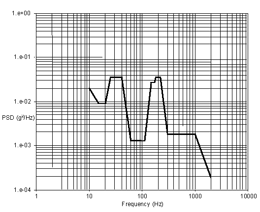
2.54 GRMS
|
Freq (Hz) |
PSD (g2/Hz) |
Freq (Hz) |
PSD (g2/Hz) |
|
5 |
2.00e-02 |
150 |
2.70e-02 |
|
10 |
2.00e-02 |
170 |
2.70e-02 |
|
15 |
9.00e-03 |
180 |
3.60e-02 |
|
20 |
9.00e-03 |
220 |
3.60e-02 |
|
25 |
3.60e-02 |
300 |
1.80e-03 |
|
40 |
3.60e-02 |
1000 |
1.80e-03 |
|
60 |
1.30e-03 |
2000 |
1.90e-04 |
|
110 |
1.30e-03 |
FIGURE 6(e). F/A-18 Buffet Lateral
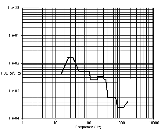
1.45 GRMS
|
Freq (Hz) |
PSD (g2/Hz) |
Freq (Hz) |
PSD (g2/Hz) |
|
5 |
4.00e-03 |
300 |
3.40e-03 |
|
15 |
4.00e-03 |
315 |
2.50e-03 |
|
25 |
1.60e-02 |
350 |
2.50e-03 |
|
35 |
1.60e-02 |
400 |
5.80e-04 |
|
55 |
4.80e-03 |
700 |
5.80e-04 |
|
110 |
4.80e-03 |
800 |
2.40e-04 |
|
120 |
2.50e-03 |
1200 |
2.40e-04 |
|
190 |
2.50e-03 |
1600 |
4.00e-04 |
|
200 |
3.40e-03 |
2000 |
4.00e-04 |
FIGURE 6(f). F/A-18 Buffet Longitudinal
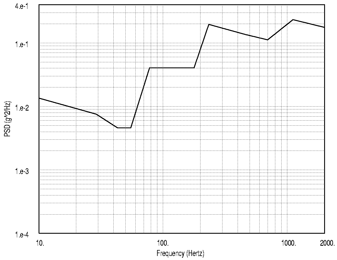
18.05 GRMS
|
Freq (Hz) |
PSD (g2/Hz) |
Freq (Hz) |
PSD (g2/Hz) |
|
10 |
1.36e-02 |
234 |
1.97e-01 |
|
29 |
7.58e-03 |
462 |
1.36e-01 |
|
43 |
4.62e-03 |
697 |
1.12e-01 |
|
55 |
4.62e-03 |
1115 |
2.34e-01 |
|
78 |
4.08e-02 |
2000 |
1.77e-01 |
|
178 |
4.07e-02 |
FIGURE 76(a). F-16 Loaded Vertical
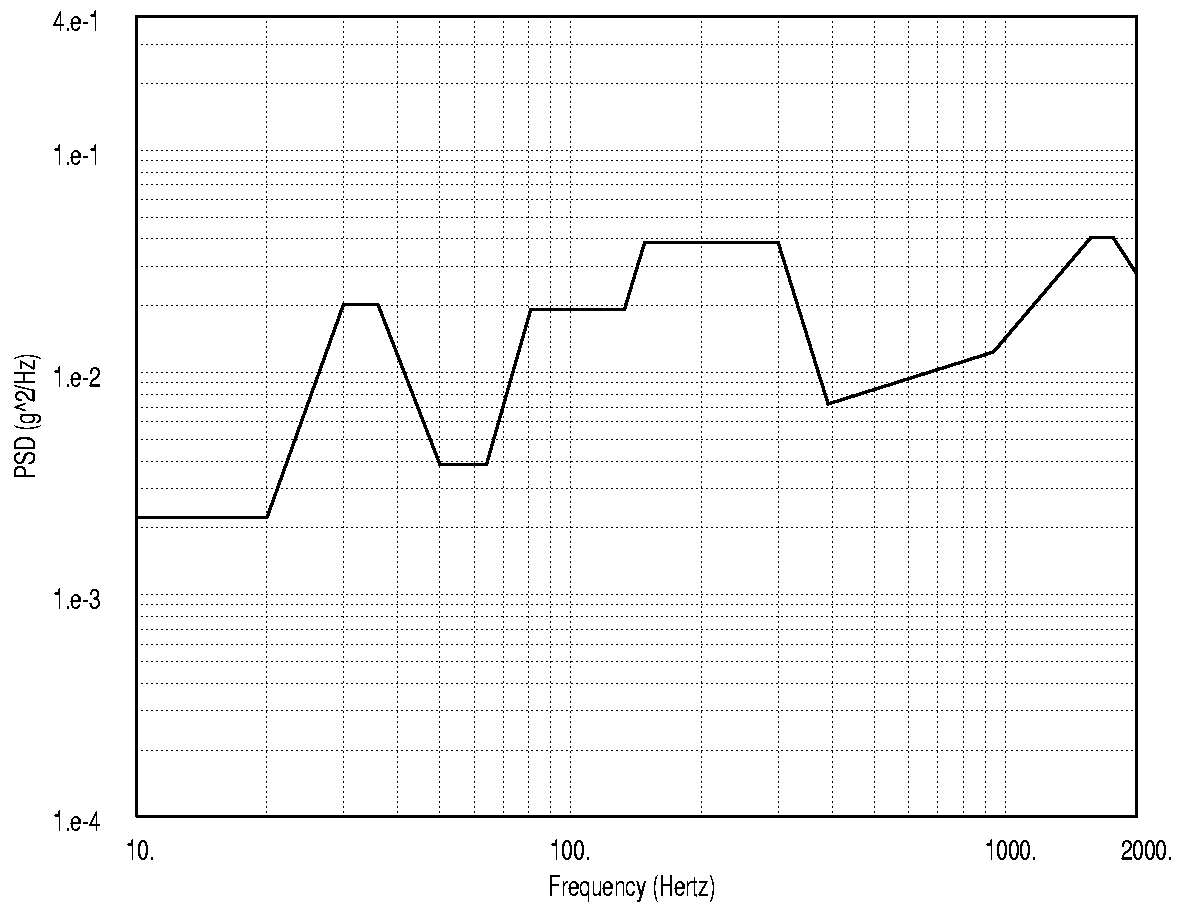
6.82 GRMS
|
Freq (Hz) |
PSD (g2/Hz) |
Freq (Hz) |
PSD (g2/Hz) |
|
10 |
2.22e-03 |
148 |
3.87e-02 |
|
20 |
2.22e-03 |
300 |
3.87e-02 |
|
30 |
2.03e-02 |
391 |
7.23e-03 |
|
36 |
2.03e-02 |
940 |
1.24e-02 |
|
50 |
3.87e-03 |
1575 |
4.06e-02 |
|
64 |
3.87e-03 |
1770 |
4.06e-02 |
|
81 |
1.93e-02 |
2000 |
2.81e-02 |
|
133 |
1.93e-02 |
FIGURE 76(b). F-16 Loaded Lateral
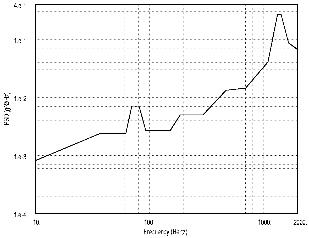
11.61 GRMS
|
Freq (Hz) |
PSD (g2/Hz) |
Freq (Hz) |
PSD (g2/Hz) |
|
10 |
8.22e-04 |
295 |
5.00e-03 |
|
37 |
2.41e-03 |
472 |
1.33e-02 |
|
62 |
2.41e-03 |
700 |
1.45e-02 |
|
70 |
7.15e-03 |
1100 |
4.09e-02 |
|
81 |
7.15e-03 |
1335 |
2.68e-01 |
|
93 |
2.68e-03 |
1435 |
2.68e-01 |
|
124 |
2.68e-03 |
1670 |
8.70e-02 |
|
152 |
2.68e-03 |
2000 |
6.71e-02 |
|
186 |
5.00e-03 |
FIGURE 76(c). F-16 Loaded Longitudinal

13.78 GRMS
|
Freq (Hz) |
PSD (g2/Hz) |
Freq (Hz) |
PSD (g2/Hz) |
|
10 |
1.55e-03 |
340 |
1.35e-01 |
|
16 |
4.57e-03 |
400 |
1.35e-01 |
|
24 |
6.74e-03 |
455 |
4.38e-02 |
|
30 |
4.05e-03 |
591 |
4.38e-02 |
|
53 |
4.05e-03 |
898 |
1.16e-01 |
|
64 |
7.44e-03 |
1123 |
1.27e-01 |
|
117 |
7.44e-03 |
1599 |
1.27e-01 |
|
185 |
5.80e-02 |
2000 |
1.11e-01 |
|
300 |
5.80e-02 |
FIGURE 76(d). F-16 Unloaded Non-Buffet Vertical
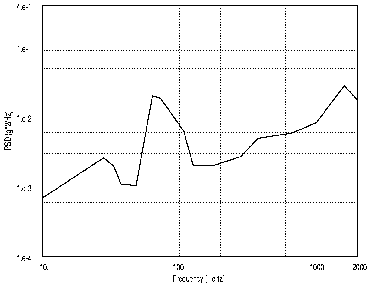
4.96 GRMS
|
Freq (Hz) |
PSD (g2/Hz) |
Freq (Hz) |
PSD (g2/Hz) |
|
10 |
7.00e-04 |
182 |
2.05e-03 |
|
28 |
2.61e-03 |
281 |
2.73e-03 |
|
33 |
1.97e-03 |
377 |
4.99e-03 |
|
37 |
1.08e-03 |
668 |
5.93e-03 |
|
48 |
1.06e-03 |
1007 |
8.37e-03 |
|
63 |
2.03e-02 |
1435 |
2.12e-02 |
|
73 |
1.86e-02 |
1611 |
2.80e-02 |
|
107 |
6.32e-03 |
2000 |
1.78e-02 |
|
126 |
2.05e-03 |
FIGURE 76(e). F-16 Unloaded Non-Buffet Lateral
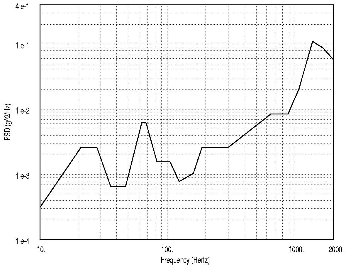
8.71 GRMS
|
Freq (Hz) |
PSD (g2/Hz) |
Freq (Hz) |
PSD (g2/Hz) |
|
10 |
3.12e-04 |
160 |
1.04e-03 |
|
21 |
2.60e-03 |
187 |
2.60e-03 |
|
28 |
2.60e-03 |
300 |
2.60e-03 |
|
36 |
6.51e-04 |
648 |
8.46e-03 |
|
47 |
6.51e-04 |
885 |
8.46e-03 |
|
63 |
6.25e-03 |
1080 |
2.08e-02 |
|
68 |
6.25e-03 |
1380 |
1.11e-01 |
|
83 |
1.56e-03 |
1670 |
8.72e-02 |
|
105 |
1.56e-03 |
2000 |
5.86e-02 |
|
124 |
7.81e-04 |
FIGURE 76(f). F-16 Unloaded Non-Buffet Longitudinal
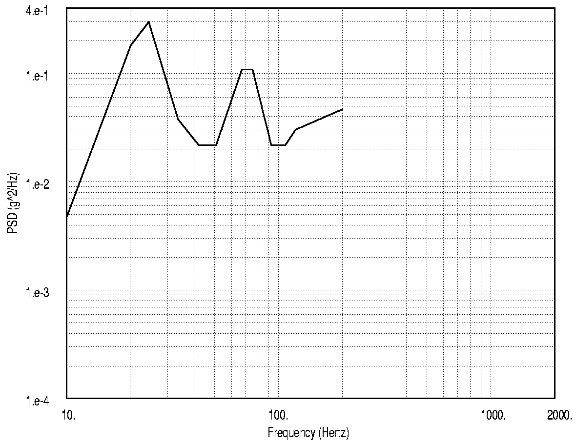
3.10 GRMS
|
Freq (Hz) |
PSD (g2/Hz) |
Freq (Hz) |
PSD (g2/Hz) |
|
10 |
4.65e-03 |
67 |
1.09e-01 |
|
20 |
1.82e-01 |
75 |
1.09e-01 |
|
24 |
2.99e-01 |
92 |
2.18e-02 |
|
34 |
3.77e-02 |
107 |
2.18e-02 |
|
42 |
2.18e-02 |
121 |
3.04e-02 |
|
51 |
2.18e-02 |
200 |
4.68e-02 |
FIGURE 76(g). F-16 Unloaded Buffet Vertical
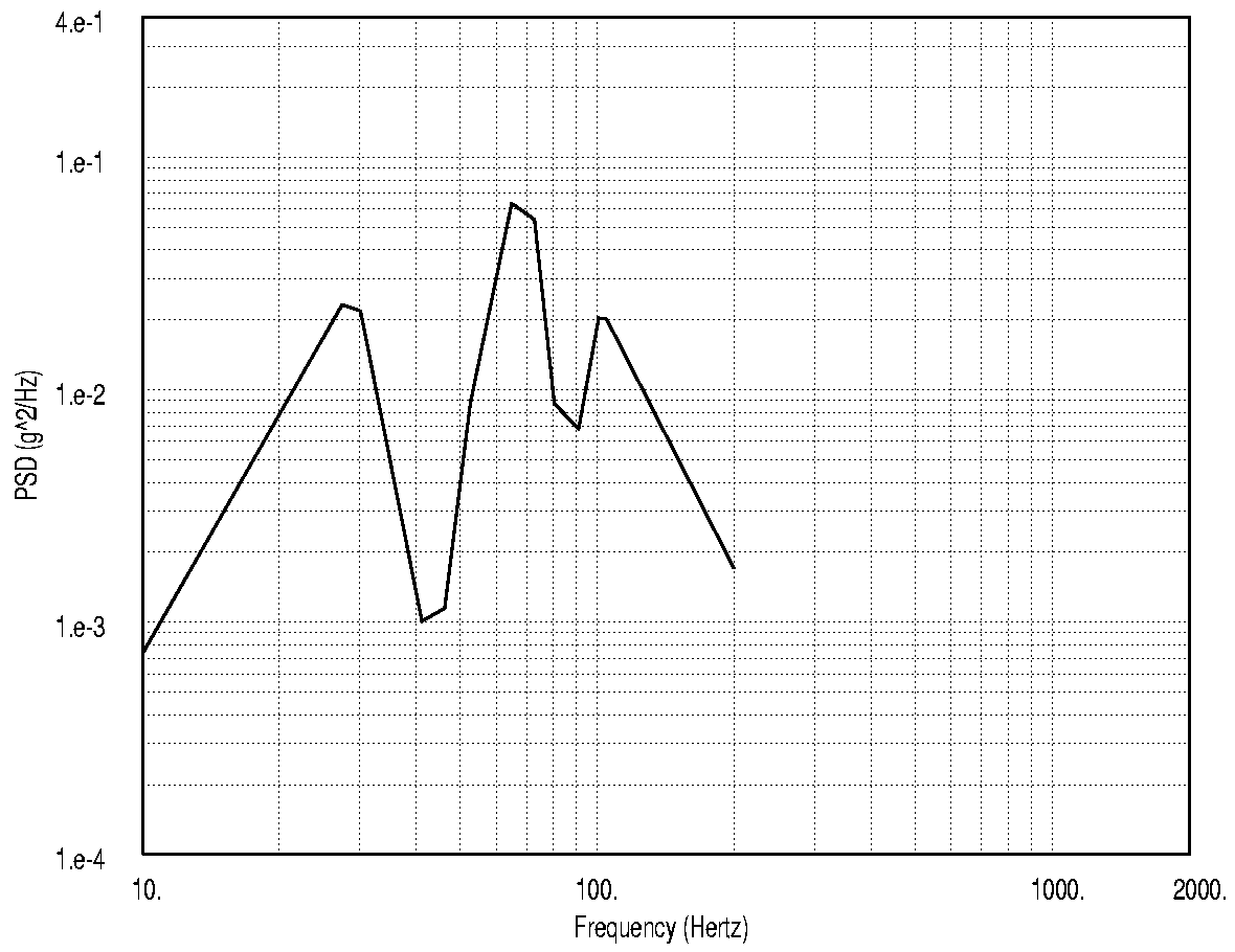
1.49 GRMS
|
Freq (Hz) |
PSD (g2/Hz) |
Freq (Hz) |
PSD (g2/Hz) |
|
10 |
7.32e-04 |
73 |
5.41e-02 |
|
27 |
2.33e-02 |
80 |
8.72e-03 |
|
30 |
2.19e-02 |
91 |
6.82e-03 |
|
41 |
1.01e-03 |
101 |
2.05e-02 |
|
46 |
1.15e-03 |
105 |
2.02e-02 |
|
53 |
8.84e-03 |
200 |
1.70e-03 |
|
65 |
6.36e-02 |
FIGURE 76(h). F-16 Unloaded Buffet Lateral

2.06 GRMS
|
Freq (Hz) |
PSD (g2/Hz) |
Freq (Hz) |
PSD (g2/Hz) |
|
10 |
1.23e-03 |
69 |
7.01e-02 |
|
20 |
1.24e-01 |
73 |
6.13e-02 |
|
24 |
1.62e-01 |
86 |
7.88e-03 |
|
37 |
2.14e-02 |
95 |
6.62e-03 |
|
44 |
5.71e-03 |
121 |
9.04e-03 |
|
47 |
6.72e-03 |
155 |
9.28e-03 |
|
52 |
1.82e-02 |
200 |
6.72e-03 |
|
63 |
6.47e-02 |
FIGURE 76(i). F-16 Unloaded Buffet Longitudinal

1.85 GRMS
|
Freq (Hz) |
PSD (g2/Hz) |
Freq (Hz) |
PSD (g2/Hz) |
|
5 |
9.40e-04 |
150 |
9.50e-03 |
|
10 |
9.40e-04 |
225 |
9.50e-03 |
|
15 |
1.20e-02 |
300 |
2.40e-03 |
|
25 |
1.20e-02 |
500 |
2.40e-03 |
|
30 |
1.80e-03 |
520 |
1.90e-03 |
|
100 |
1.80e-03 |
2000 |
4.80e-04 |
FIGURE 7(a). Non-Buffet Vertical

3.63 GRMS
|
Freq (Hz) |
PSD (g2/Hz) |
Freq (Hz) |
PSD (g2/Hz) |
|
5 |
3.20e-03 |
150 |
1.40e-02 |
|
10 |
3.20e-03 |
175 |
4.20e-02 |
|
20 |
7.00e-03 |
225 |
4.20e-02 |
|
35 |
7.00e-03 |
235 |
3.20e-02 |
|
40 |
9.70e-03 |
250 |
3.20e-02 |
|
50 |
9.70e-03 |
300 |
6.40e-03 |
|
60 |
1.60e-03 |
1000 |
6.40e-03 |
|
70 |
1.60e-03 |
2000 |
1.30e-03 |
|
80 |
1.40e-02 |
FIGURE 7(b). Non-Buffet Lateral

1.41 GRMS
|
Freq (Hz) |
PSD (g2/Hz) |
Freq (Hz) |
PSD (g2/Hz) |
|
5 |
3.40e-04 |
200 |
2.30e-03 |
|
15 |
3.40e-04 |
315 |
2.30e-03 |
|
20 |
6.90e-04 |
330 |
1.80e-03 |
|
100 |
6.90e-04 |
335 |
1.70e-03 |
|
110 |
4.50e-04 |
400 |
1.70e-03 |
|
190 |
1.75e-03 |
2000 |
5.90e-04 |
|
195 |
2.00e-03 |
FIGURE 7(c). Non-Buffet Longitudinal

2.07 GRMS
|
Freq (Hz) |
PSD (g2/Hz) |
Freq (Hz) |
PSD (g2/Hz) |
|
5 |
3.40e-02 |
200 |
7.40e-03 |
|
10 |
3.40e-02 |
295 |
1.70e-03 |
|
15 |
4.20e-02 |
400 |
1.70e-03 |
|
20 |
1.10e-01 |
1200 |
3.00e-04 |
|
25 |
1.10e-01 |
2000 |
3.00e-04 |
|
40 |
7.40e-03 |

2.54 GRMS
|
Freq (Hz) |
PSD (g2/Hz) |
Freq (Hz) |
PSD (g2/Hz) |
|
5 |
2.00e-02 |
150 |
2.70e-02 |
|
10 |
2.00e-02 |
170 |
2.70e-02 |
|
15 |
9.00e-03 |
180 |
3.60e-02 |
|
20 |
9.00e-03 |
220 |
3.60e-02 |
|
25 |
3.60e-02 |
300 |
1.80e-03 |
|
40 |
3.60e-02 |
1000 |
1.80e-03 |
|
60 |
1.30e-03 |
2000 |
1.90e-04 |
|
110 |
1.30e-03 |

1.45 GRMS
|
Freq (Hz) |
PSD (g2/Hz) |
Freq (Hz) |
PSD (g2/Hz) |
|
5 |
4.00e-03 |
300 |
3.40e-03 |
|
15 |
4.00e-03 |
315 |
2.50e-03 |
|
25 |
1.60e-02 |
350 |
2.50e-03 |
|
35 |
1.60e-02 |
400 |
5.80e-04 |
|
55 |
4.80e-03 |
700 |
5.80e-04 |
|
110 |
4.80e-03 |
800 |
2.40e-04 |
|
120 |
2.50e-03 |
1200 |
2.40e-04 |
|
190 |
2.50e-03 |
1600 |
4.00e-04 |
|
200 |
3.40e-03 |
2000 |
4.00e-04 |
FIGURE 7(f). Buffet Longitudinal
3.2.6.5 Shock.
3.2.6.5.1 Maintenance, transportation, and storage.
3.2.6.5.1.1 Transit drop. The Smart Rack shall operate satisfactorily after exposure to a 24-inch drop onto a concrete surface on the left and right bottom edges and on the bottom face for a total of 3 drops.
3.2.6.5.1.2 Rail impact. The Smart Rack shall operate satisfactorily after exposure to a 25-g, 25-millisecond half sine pulse applied in the positive and negative direction of the longitudinal axis.
3.2.6.5.2 Captive carriage. The Smart Rack shall operate satisfactorily during and after exposure to the catapult launch, arrested landing, and adjacent store ejector shock environments defined in Table 8. The shock pulses specified in Table 8 shall be applied in the positive and negative direction of each axis and shall resemble a half-sine wave.
|
Type |
Axis |
Amplitude (g’s) |
Duration (msec) |
|
Carrier Suitability Shock |
Lateral |
6.2 |
35 |
|
Vertical |
8.6 |
100 |
|
|
Longitudinal |
6.0 |
600 |
|
|
Adjacent Store Ejection Shock |
Lateral |
37.0 |
19 |
|
Vertical |
32.0 |
19 |
3.2.6.6 Acceleration.
The Smart Rack shall operate satisfactorily during and after exposure to the wing mounted captive carriage inertia load limits as defined in MIL-A-8591.3.2.6.7 Static loads. Structural modification to the baseline CVER/VER shall be designed to meet the required operational usage (carriage loads, launch, recovery, ground loads, and dynamic release loads) resulting from the critical store loads for the Air Force F-16 and the Navy F/A-18. The BRU-55/A and BRU-57/A shall operate satisfactorily after exposure to the limit air loads defined in Table 9 and Table 10 respectively. The limit loads of Table 9 and Table 10 are applied to the JSOW c.g. location. The effects of deformation remaining after the application of the yield loads as defined in 3.2.3.6.1 shall not affect form, fit, or function of the Smart Rack. The Smart Rack shall not fail catastrophically during application of the ultimate loads as defined in 3.2.3.6.2.
TABLE 9. F/A-18 Limit Loads
|
Limit Loads |
|||||||||||
|
Condition |
Fx |
Fy |
Fz |
Mx |
My |
Mz |
|||||
|
7F-RPO |
1,053 |
1,833 |
-10,487 |
3,687 |
8,487 |
35,827 |
|||||
|
9F-RPO |
1,087 |
-1,380 |
- 10,513 |
3,160 |
7,853 |
26,547 |
|||||
|
31F-1G-360 |
727 |
1,853 |
- 3,473 |
6,740 |
8,640 |
73,640 |
|||||
|
32F-1G-360 |
727 |
1,100 |
- 3,727 |
4,720 |
2,227 |
87,373 |
|||||
|
49F-WUT |
867 |
967 |
- 8,780 |
- 3,140 |
14,713 |
- 58,827 |
|||||
|
54F-MAX-Catapult |
6,073 |
0 |
-1,780 |
0 |
- 5,080 |
0 |
|||||
Loads in Pounds, Moments in Inch-Pounds
TABLE 10. F-16 Limit Loads
|
Limit Loads |
||||||||||||
|
Load Case No. |
Fx |
Fy |
Fz |
Mx |
My |
Mz |
||||||
|
6769 |
3,570 |
2,285 |
-436 |
4,169 |
-158,076 |
-59,193 |
||||||
|
7634 |
2,785 |
2,490 |
2,415 |
3,463 |
-86,874 |
109,614 |
||||||
|
6393 |
2,854 |
4,586 |
-6,918 |
9,166 |
-60,188 |
40,765 |
||||||
|
7354 |
2,725 |
5,011 |
-588 |
2,016 |
-76,154 |
109,440 |
||||||
|
5599 |
-429 |
5,798 |
-10,772 |
8,133 |
119,107 |
81,727 |
||||||
|
5696 |
-429 |
6,821 |
-8,088 |
8,133 |
119,107 |
92,925 |
||||||
|
5689 |
2,742 |
7,379 |
-6,484 |
10,876 |
25,868 |
99,225 |
||||||
Loads in Pounds, Moments in Inch-Pounds
3.2.6.8 Acoustic noise. The Smart Rack shall operate satisfactorily during and after exposure to the performance and after exposure to the endurance acoustic noise levels defined in Table 11 and Figure 8.
TABLE 11. Acoustic Noise Environment - Duration
|
Test Type |
Overall Sound Pressure Level (dB re 0.0002 Dyne/cm2) |
Duration (minutes) |
|
Performance |
159.2 |
30 |
|
Endurance |
165.2 |
21 |
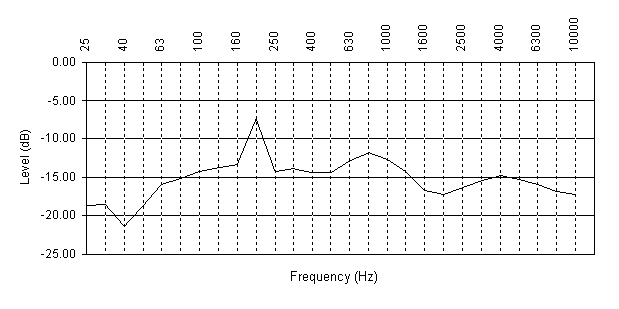
|
Center Frequency (Hz) |
Level Note 1 (dB) |
Center Frequency (Hz) |
Level Note 1 (dB) |
|
25 |
-18.7 |
630 |
-12.8 |
|
31.5 |
-18.5 |
800 |
-11.8 |
|
40 |
-21.4 |
1000 |
-12.7 |
|
50 |
-18.7 |
1250 |
-14.2 |
|
63 |
-15.9 |
1600 |
-16.7 |
|
80 |
-15.2 |
2000 |
-17.2 |
|
100 |
-14.2 |
2500 |
-16.3 |
|
125 |
-13.7 |
3150 |
-15.4 |
|
160 |
-13.3 |
4000 |
-14.8 |
|
200 |
-7.4 |
5000 |
-15.3 |
|
250 |
-14.2 |
6300 |
-15.9 |
|
315 |
-13.9 |
8000 |
-16.8 |
|
400 |
-14.4 |
10000 |
-17.2 |
|
500 |
-14.4 |
Note 1 - Referenced to Overall Sound Pressure Level (OSPL)
FIGURE 8. One Third Octave Band Noise Levels
3.2.6.10 Dust. The Smart Rack shall operate satisfactorily after exposure to a blowing dust environment for six hours. The dust concentration shall be 10.6 grams/meter3 with a corresponding wind velocity of 1750 ft/min.
3.2.6.11 Rain. The Smart Rack shall operate satisfactorily after exposure to a 4 inch/hour rain rate with a corresponding 40 mph horizontal wind velocity for 30 minutes per exposed face.
3.2.6.12 Fungus. The Smart Rack materials shall not be degraded when exposed to a fungus environment for 28 days. Fungus such as aspergillus niger, aspergillus flavus, aspergillus versicolor, penicillium funiculosum, and chaetomium globosum shall be considered. Overall spraying shall not be necessary to meet this requirement.
3.2.6.13 Fluid contamination. The Smart Rack shall operate satisfactorily after exposure to the effects of oil, grease, hydraulic fluids, jet fuel, deicing fluids and cleaning solutions as defined in Table 12.
|
Contaminate |
National Stock Number |
Type/Standard |
|
Aircraft Engine Oil |
9150-01-414-8141 |
MIL-PRF-7808 or MIL-PRF-23699 |
|
Aircraft Fuel JP-5 or JP-4 |
9130-00-273-2380 |
MIL-PRF-5624 |
|
Aircraft Hydraulic Fluid |
9150-00-252-6383 9150-01-009-7709 |
MIL-PRF-83282 |
|
Cleaning Compound, Aircraft Surface |
6850-01-248-9828 |
MIL-PRF-85570 |
|
De-Icing Fluid |
6850-LL-000-0011 |
Water/Glycol (85%/15%) mixture |
3.2.6.14 Electromagnetic environmental effects (E3) performance. The Smart Rack shall be designed, analyzed, installed and tested to perform its mission in the worldwide electromagnetic environment (EME) without any malfunction or degradation of performance. The E3 design shall include, but not be limited to: Electromagnetic Compatibility (EMC), Electromagnetic Interference (EMI), Emission Control (EMCON), Precipitation Static (P-Static), Electrostatic Discharge (ESD), lightning, bonding, grounding, and Hazards of Electromagnetic Radiation to; Personnel (HERP), Ordnance (HERO), and Fuel (HERF). The Smart Rack shall operate without damage within the required performance levels during and after exposure to these specified environmental conditions.
3.2.6.14.1 Electromagnetic interference. The electromagnetic emissions and susceptibilities of the Smart Rack and interfaces, both conducted and radiated, shall meet the performance requirements as specified in the following subparagraphs. They shall also meet the performance requirements of the following paragraphs when installed on the aircraft. The Smart Rack shall be compatible with all other
electronic subsystems on the aircraft, and shall include the necessary timing and control circuits to prevent mutual interference. The Smart Rack shall be compatible in their intended installation location with the aircraft external environment and shall be grounded and bonded to protect it from the effects of lightning to the aircraft fuselage.
3.2.6.14.1.1 Conducted emissions. The Smart Rack shall not conduct any EMI beyond specified limits while operating on the aircraft. The equipment shall conform to the requirements listed in the following paragraphs.
3.2.6.14.1.1.1 Conducted emissions on power lines. Electromagnetic emissions in the frequency range of 0.010 to 10 Megahertz (MHz), shall not appear on the Smart Rack power leads in excess of the values shown in Figure 9 for emissions.
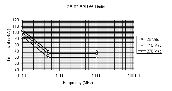
FIGURE 9. Conducted Emissions on Power Lines
3.2.6.14.1.1.2 Conducted susceptibility. The Smart Rack shall not incur permanent damage or be susceptible while operating on the aircraft due to conducted interference. The equipment shall conform to the requirements of the following paragraphs.
3.2.6.14.1.1.2.1 On power lines 30 Hz to 50 kHz. The Smart Rack shall not exhibit any malfunction, degradation of performance, or deviation from specified indications, beyond the tolerances indicated in the individual equipment or subsystem specifications when subjected to electromagnetic energy injected onto its power leads equal to the values shown on Figure 10.
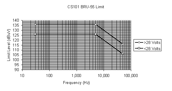
FIGURE 10. Conducted Susceptibility on Power Lines
3.2.6.14.1.1.2.2 Bulk cable injection, 0.01 to 400 MHz. The Smart Rack shall not exhibit any malfunction, degradation of performance, or deviation from specified indications, beyond the tolerances indicated in the individual equipment or subsystem specifications when subjected to the frequencies and amplitudes as shown on Figure 11.
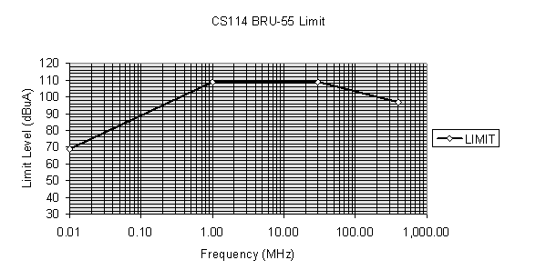
FIGURE 11. Conducted Susceptibility, Bulk Cable Injection
3.2.6.14.1.1.2.3 Bulk cable injection, impulse excitement. The Smart Rack shall not exhibit any malfunction, degradation of performance, or deviation from specified indications, beyond the tolerances indicated in the individual equipment or subsystem specifications when subjected to the test impulse as shown in Figure 12 at a 30 Hz rate for one minute.
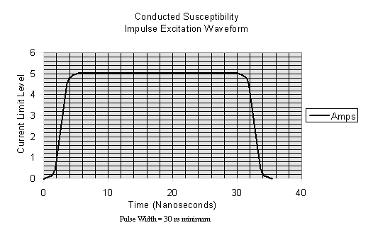
FIGURE 12. Conducted Susceptibility, Bulk Cable Injection Impulse
3.2.6.14.1.1.2.4 From common mode transients. The Smart Rack shall not exhibit any malfunction, degradation of performance, or deviation from specified indications, beyond the tolerances indicated in the individual equipment or subsystem specifications when subjected to damped sinusoid pulses and common mode transients as described by Figures 13 and 14.
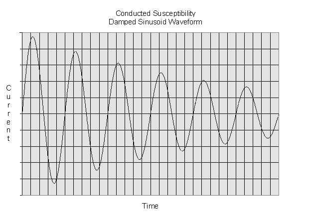
NOTES: 1. Normalized wave form: e -(P F T)/Q sin(P F T)
Where:
F = Test frequency (Hz)
T = Time (sec)
Q = Damping factor, 15 + 5
2. Damping factor (Q) shall be determined as follows:
Q = P (n-1) / In(IP/IN)
Where:
Q = Damping factor
N = Cycle number (i. e. N = 2, 3, 4, 5.....)
IP = Peak current at first cycle
IN = Peak current at NTH cycle
In = Natural log
3. IP shall be per Figure 13
FIGURE 13. Conducted Susceptibility for Damped Sinusoid Transients

FIGURE 14. Conducted Susceptibility for Common Mode Transients
3.2.6.14.1.1.2.5 From ground plane noise. The Smart Rack interface circuits shall be capable of specified performance when subjected to the following aircraft chassis noise, between the ground plane and the individual WRAs:
a. 3 V rms from 320 Hz to 500 Hz, limited to 10 A rms maximum.
b. 1 V rms from 500 Hz to 50 kHz, limited to 150 mA rms maximum.
c. 1 V rms from 50 kHz to 100 MHz, limited to 150 mA rms maximum.
d. + 8 V, 100 m sec pulses at a repetition rate of 100 pulses per second (pps), limited to 15 A peak.
e. + 8 V, 10 m sec pulses at a repetition rate of 1000 pps, limited to 15 A peak.
f. + 8 V, 5 m sec pulses at a repetition rate of 1000 pps, limited to 15 A peak.
g. + 8 V, 0.15 m sec pulses at a repetition rate of 50 pps, limited to 15 A peak.
3.2.6.14.1.1.3 Radiated emissions. Electromagnetic emissions in the frequency range of 10 kHz to 18 Gigahertz (GHz) shall not be radiated in excess of the values shown in Figure 15. Above 30 MHz, the limits shall be met for both horizontally and vertically polarized waves.
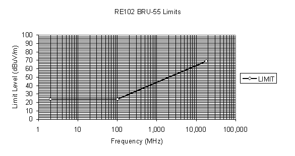
3.2.6.14.1.1.4 Radiated susceptibility. The Smart Rack shall not incur permanent damage or be susceptible whilte operating on the aircraft in an electromagnetic environment. The equipment shall conform to the requirements listed in the following paragraphs.
3.2.6.14.1.1.4.1 From electric fields. The Smart Rack shall not exhibit any malfunction, degradation of performance, or deviation from specified indications, beyond the tolerances indicated in the individual equipment or subsystem specifications when subjected to a 200 volts per meter (V/m) fieold, 1 meter away from the source, with the frequency range of 14 kHz to 40 GHz.
3.2.6.14.1.1.4.2 From relay switching transients. The Smart Rack shall not exhibit any malfunction, degradation of performance, or deviation from specified indications, beyond the tolerances indicated in the individual equipment or subsystem specifications when subjected to relay switching transients of + 600 V peak.
3.2.6.14.2 Filtering. The Smart Rack interface shall contain RF noise suppression components on all noisy or susceptible circuits and shall contain noise isolation components at all ports of noise exit and entry.
3.2.6.14.3 Grounding. The external grounding system of the Smart Rack shall be compatible and consistent with the following aircraft grounding scheme. The Smart Rack shall be grounded in such a manner as to prevent ground loops and common ground returns for signal and power circuits, provide effective shielding for signal circuits, minimize EMI, and protect personnel from electrical shock hazards. The following shall apply:
3.2.6.14.3.1 Chassis. A wire of minimum length connected internally to the WRA chassis shall be provided at a pin on each primary power connector. No circuit shall be allowed to utilize this wire as its primary return.
3.2.6.14.3.2 Primary power. For grounding purposes, primary power is defined as electrical power which is conducted from aircraft generators or power supplies. This definition includes aircraft bus power which is fused, switched, filtered, or attenuated. A return for each source of primary power used in the Smart Rack, whether grounded to the internal chassis or not, shall be made available at a separate pin of each primary power connector.
3.2.6.14.3.3 Secondary power and signal. Secondary power is defined as electrical power which is derived or isolated from primary power by a transformer or other electronics. A signal is defined as electrical energy which contains information. The following requirements apply to the electrical interfaces among WRAs.
a. Signal and secondary power circuits may share return wires with other such circuits only when approved by the procuring activity in writing. Analog video and other wideband analog (non-digital) signals with information frequency content above 1 MHz may be conducted between WRAs on triax with corresponding triax connectors only if approved by the procuring activity in writing. The signal shall be terminated in a balanced load which matches the characteristic impedance of the line.
b. The impedance of unbalanced signal sources operating into balanced loads shall be sufficiently low to avoid unbalancing the interface circuits to the extent that the circuits are susceptible to the aircraft chassis noise levels of 3.2.6.14.1.1.2.5. 5.1.16.1.2.5.
c. Signal sources which operate into unbalanced loads (in off-the-shelf type equipment) shall be isolated from aircraft structure by a large enough impedance to ensure compatibility with the aircraft chassis noise level of 3.2.6.14.1.1.2.5. 3.2.5.1.16.1.2.5.
d. Signals containing radio frequencies (RF) or intermediate frequency (IF) carriers above 2 MHz shall be referenced to chassis at each end and shall be impedance matched to the transmission line.
e. Aircraft structure shall be used as a return for discrete signals exceeding 10 V, provided the receptor circuits are thresholded so as to reject the above referenced aircraft chassis noise level.
3.2.6.14.3.4 Shield. A separate connector pin shall be provided for each aircraft wire shield. The connector shield pins shall be grounded to the equipment chassis inside the WRA without introducing adverse antenna effects.
3.2.6.14.3.5 Component. All externally exposed metal parts, shields, control shafts, switch handles, connectors, bushings, etc. shall be grounded to the chassis.
3.2.6.14.4 Bonding. A means of electrically bonding all elements of the equipment to the aircraft chassis shall be provided. Bonding resistance between the bonding surface and all parts of the equipment case shall not exceed 2.5 milliohms (mW ).
3.2.6.14.5 Shielding gaskets. Shielding gaskets and similar devices for RF applications shall avoid the use of materials which represent severe dissimilar metal combinations with the interfaces they contact such as silver, monel, or silver filled aluminum surfaces. In addition, all RF shielding gaskets shall incorporate a weather seal on the exterior side which shall overlap any exposed, nonpainted metal surfaces.
3.2.6.14.6 Lightning. All Smart Rack WRA installations within the aircraft shall provide protection against lightning in accordance with the following paragraph. A 6 decibel (dB) safety margin shall be applied to WRAs or SRAs for direct or indirect lightning effects.
3.2.6.14.6.1 Lightning protection. The Smart Rack shall be provided protection at all possible points of lightning entry affected by the Smart Rack installation. Bonding shall be accomplished to achieve protection against lightning discharge current carried between extremities of an airborne vehicle without risk of damaging flight controls or producing sparking or voltages within the vehicle in excess of 500 V. Individual bonding jumpers for lightning protection shall be of sufficient gage to safely conduct the current. Soldered connections shall not be used on jumpers required to carry lightning currents.
3.2.6.14.7 Electromagnetic Radiation Hazards to Ordnance (HERO). The Smart Rack shall meet the HERO requirements as follows. To prevent accidental triggering of EEDs, Smart Rack shall not be HERO susceptible to the external EME listed in Table 13.
3.2.6.14.8 Electromagnetic compatibility (EMC). The Smart Rack shall not interfere with, or be interfered by, the operation of any other aircraft equipment. The Smart Rack shall not incur any degradation or permanent damage while operating on the aircraft.
3.2.6.14.9 Electrical power. The Smart Rack shall not malfunction nor have unacceptable responses when supplied with aircraft and ground generated electrical power. This specifically includes surges, ripples, voltages, and other electrical conditions that can cause interference or susceptibility.
3.2.6.14.10 Commercial subsystems/equipment. When commercial off the shelf equipment is considered for use as part of the Smart Rack, the following E3 performance requirements shall apply in selecting and utilizing such equipment:
a. The equipment may be considered adequate if the system requirements are not significantly more stringent than those to which the equipment was designed, and interference test reports are available to adequately demonstrate compliance; however, compliance with the requirements relating to subsystems and equipment shall not relieve the contractor of providing system compatibility. When compliance with interference requirements cannot be substantiated due to unavailability of test reports, the contractor may perform laboratory interference tests for qualification of the subsystem as negotiated with the procuring activity.
b. After evaluation of the data, if it is determined that more stringent requirements are necessary, it shall be the responsibility of the contractor to implement these requirements, or select another equipment with adequate characteristics.
3.2.6.14.11 Electromagnetic environment (EME). The Smart Rack when installed on the aircraft shall operate satisfactorily in the EME of friendly and hostile emitters. The Smart Rack shall not incur any degradation or permanent damage while operating in the aircraft’s EME. The carrier deck and aircraft operational EME requirements are shown in Table 13.
TABLE 13. Electromagnetic Environment
|
Frequency (MHz) |
Modulation (Volts/Meter) |
Power Density (mW/cm2) |
Volts/ Meter |
||
|
2 - 30 |
AM |
90% 1 kHz sine wave |
10.6 |
200 |
|
|
215 - 225 |
PAM |
10 m sec PW |
200 pps |
10.6 |
200 |
|
215 - 225 |
PAM |
200 m sec PW |
200 pps |
10.6 |
200 |
|
400 - 450 |
PAM |
4 m sec PW |
200 pps |
25 |
310 |
|
850 - 940 |
PAM |
2 m sec PW |
1000 pps |
200 |
870 |
|
850 - 940 |
PAM |
125 m sec PW |
300 pps |
200 |
870 |
|
1215 -1365 |
PAM |
10 m sec PW |
3000 pps |
10.6 |
200 |
|
1260 -1400 |
PAM |
5 m sec PW |
3000 pps |
25 |
310 |
|
2900 - 3100 |
PAM |
3 m sec PW |
1000 pps |
17500 |
8100 |
|
2900 - 3100 |
PAM |
70 m sec PW |
200 pps |
17500 |
8100 |
|
3100 - 3500 |
PAM |
10 m sec PW |
3000 pps |
50000 |
13700 |
|
3100 - 3500 |
PAM |
50 m sec PW |
3000 pps |
50000 |
13700 |
|
3550 - 3700 |
PAM |
1 m sec PW |
1000 pps |
2500 |
3000 |
|
5400 - 5800 |
PAM |
1 m sec PW |
600 pps |
320 |
1100 |
|
9000 - 9160 |
PAM |
0.5 m sec PW |
1000 pps |
500 |
1375 |
|
9300 - 9400 |
PAM, |
0.2 m sec PW |
1000 pps |
40 |
390 |
|
13500 - 14500 |
PAM |
0.2 m sec PW |
50000 pps |
40 |
390 |
|
15400 - 15700 |
PAM |
0.2 m sec PW |
50000 pps |
10.6 |
200 |
|
33000 - 33400 |
PAM |
0.2 m sec PW |
2000 pps |
2500 |
3070 |
|
Frequency (Hz) |
Environment (V/m - rms) |
|
|
Peak |
Average |
|
|
10k-150M |
200 |
200 |
|
150M-225M |
200 |
200 |
|
225M-400M |
2,830 |
240 |
|
400M-700M |
4,000 |
750 |
|
700M-790M |
3,500 |
240 |
|
790M-1000M |
3,500 |
610 |
|
1G-2G |
5,670 |
1000 |
|
2G-2.7G |
21,270 |
850 |
|
2.7G-3.6G |
27,460 |
1,230 |
|
3.6G-4G |
21,270 |
850 |
|
4G-5.4G |
15,000 |
610 |
|
5.4G-5.9G |
15,000 |
1,230 |
|
5.9G-6G |
15,000 |
610 |
|
6G-7.9G |
12,650 |
670 |
|
7.9G-8G |
12,650 |
810 |
|
8G-14G |
21,270 |
1,250 |
|
14G-18G |
21,270 |
614 |
|
18G-40G |
5,000 |
750 |
3.2.6.14.12 Emission control. When installed aboard the aircraft the Smart Rack shall not radiate in excess of 110 dBm per meter squared at a distance of 1 nautical mile in the frequency range of 500 kHz to 40 GHz when measured with a bandwidth of 100 kHz or less.
3.2.6.14.13 Electrostatic discharge protection (ESD). The Smart Rack WRAs and SRAs shall not be susceptible to electrostatic discharge or electric field damage during operation, handling, test, storage, and shipping. All devices which have been identified as sensitive to ESD or electric fields, or are susceptible to damage from excessive current flow through the junction, that are interfaced directly with the external connectors (input, output, and test) shall be able to withstand an ESD pulse of 2000 V (for assemblies) and 4000 V (for equipment) for a duration of 1 to 3 nanoseconds (nsec) or a current flow of 500 mA through the junction of the device.
All components or assemblies which are susceptible to damage or degradation due to electrostatic discharge (ESD) shall be marked IAW best industry standards and practices. Marking shall be in a location visible during maintenance actions if possible.
3.3 Design and construction.
3.3.1 Commonality and maintainability. The Smart Rack ECA shall be designed to facilitate commonality and maintainability. To the maximum extent practical the design shall be partitioned into assemblies and subassemblies that will facilitate both fault isolation and replacement of faulty SRAs economically. The partitioning of the ECA and associated wiring shall be done in a manner to maximize commonality of the two configurations (BRU-55/A and BRU-57/A). For example the EBF and EBF interfaces (BRU-55/A) shall be designed as a self-contained assembly with subassemblies as necessary to meet the maintainability requirement.
3.3.2 Materials, processes and parts. Attention shall be given to the application and use of materials, processes and parts that facilitate interchangeability,. Sstocking and replacement in service. Materials shall also be chosen on the basis of suitability and availability in this country. Non-critical materials shall be used when performance, interchangeability or reliability will not be adversely affected.
3.3.2.1 Hazardous materials. The Smart Rack shall comply with the ASC Hazardous Material Reduction Program guidance in Appendix I.
3.3.2.2 Corrosion prevention and control. Corrosion prevention and control shall be accomplished by using resistant materials and best commercial and/or military practices. The materials and practices shall be consistent with the environments of 3.2.6.
3.3.2.3 Surface finishes. Selection of surface finish parameters for protective/paint systems shall include but not be limited to the following: system compatibility, smokeless emission behavior, durability, stability, and abrasion, heat, and corrosion resistance. Paint shall match that used on the F-16 for the BRU-57 (color number 36270) and the F/A-18 for the BRU-55 (color number 36375).
3.3.3 Workmanship. Workmanship of the Smart Rack shall exhibit high quality electronic practices and ensure safety, proper and dependable operation and service life. The Smart Rack modifications shall be constructed to produce a product free from all defects which would affect proper functioning in service. Particular attention shall be given to thoroughness of assembly, alignment of parts, tightness of fasteners, marking of parts, protective finishes and removal of burrs and sharp edges.
3.3.4 Interchangeability. Design tolerances shall permit Smart Rack parts, subassemblies and assemblies to be used in their parent assemblies without regard to the source of supply or manufacture. The electronic SRAs shall be interchangeable between the Services to the maximum extent practical. Changes in vendor's part numbers, nomenclature and type designation shall be consistent with current inventory and configuration management practices and shall be subject to Ggovernment approval.
3.3.5 Safety. The Smart Rack shall support efficient personnel performance under all operating conditions and environments. Special attention shall be given to the design of electronic equipment to provide fail safe features for safety of personnel during the installation, operation, maintenance and repair of the Smart Rack components.
3.3.5.1 Personnel safety. The Smart Rack shall be designed to minimize the probability and severity of injury to personnel. All materials shall be non-toxic and non-combustible.
3.3.5.2 Mechanical safety. Safeguards shall be installed to prevent inadvertent actuation of controls and entrapment of body parts and clothing in moving parts, when utilized.
3.3.5.3 Electrical safety. Accidental contact with current carriers such as current carrying components, terminals and like devices which have potentials greater than 70 V rms with respect to ground shall be guarded from accidental contact by personnel if such points are exposed to contact during direct support or operator maintenance.
3.3.5.4 Operational safety The SMART
RACK electrical design shall provide for positive control of power application to implement all safety related functions such as weapon release, jettison, and arming solenoid activation.3.3.5.4.1 Release consent interface. The Smart Rack shall require release consent from the aircraft to implement any rack safety critical function.
3.3.5.4.2 CSSI power and discrete signals. The Smart Rack shall not activate any power signals or discretes at the CSSIs unless commanded by the aircraft.
3.3.6 Human performance and engineering. Human engineering principles shall be applied in accordance with an approach proposed by the contractor. The contractors approach shall address:
a. Physical measures to preclude interchange of units or components of same or similar form that are not functionally interchangeable.
b. Physical measures to preclude improper mounting of components or units.
c. Measures (e.g., coding) to facilitate identification and interchange of interchangeable units or components.
d. Measures (e.g., alignment pins) to facilitate proper mounting of units and components.
e. Measures to ensure that identification, orientation, and alignment provisions include cables and connectors.
f. No components shall be accessible externally which would allow accidental or inadvertent operation of the Smart Rack.
g. All O-level service and normal function operations shall be accessible with the store(s) fully latched and restrained.
h. Criteria shall be applied to the design to: (1) assure that the equipment can be efficiently, safely, and reliably maintained and operated; (2) preclude human error type failures; (3) assure that design features will not constitute a hazard to personnel.
i. The design of the Smart Rack shall be such that there are no protrusions or critically located component that could easily be damaged by normal handling of the Smart Rack.
3.4 Personnel and training.
3.4.1 Personnel. The Smart Rack shall be designed for operation, test, removal and replacement of faulty SRAs by personnel with the same skill level as those qualified to troubleshoot, test and repair the existing CVER. The ECA’s SRAs shall be designed for testing, troubleshooting, and repair by maintenance personnel having knowledge and skills equivalent to that of the Navy's Avionics Technician rating.
3.4.2 Training. The design, fabrication and operation of the Smart Rack shall minimize the time required to train operators and maintenance personnel, when compared with the training requirements by the personnel with the same skill level as those qualified on the CVER/VER.
3.4.2.1 Maintenance. System maintenance at the I-level will be carried out by personnel having knowledge and skills equivalent to those of the Navy’s Avionics Technician rating. technicians with comparable military occupational skills as those who presently maintain the baseline CVER/VER.
3.4.2.1.1 Organizational level. Training will consist of Smart Rack peculiar flight line maintenance and release and control checks.
3.4.2.1.2 Intermediate level. Training will consist of test and repair procedures.
3.5 Logistics.
3.5.1 Maintenance. The Smart Rack shall be designed so that with the exceptions identified herein no additional maintenance tasks are required for operation and use of the Smart Rack. Routine maintenance of ejector units will be performed and is not considered an additional task.
3.5.1.1 Organizational maintenance. Maintenance at the O-level shall be limited to testing, fault detection, and removal and replacement tof the defective WRA.
3.5.1.2 Intermediate maintenance. Maintenance at the l-level shall be limited to testing, fault detection, fault isolation and removal and replacement to the defective WRA or SRA of the Smart Rack ECA.
3.5.1.3 Depot maintenance. The Smart Rack shall not require depot maintenance.
3.5.2 Supply. The Smart Rack will require revision to existing supply support resources.
3.5.3 Facility and facility equipment. No new facilities shall be required.
3.5.4 Support equipment. Design of the Smart Rack shall not require any new or modified support equipment for test and troubleshooting, except as specified in 3.2.5.4.
3.5.5 Handling equipment. The Smart Rack shall not require new handling equipment or modifications to existing CVER/VER handling equipment. The Smart Rack shall retain the capability of uploading and downloading of mission stores using standard manual hoisting and lifting equipment, the Single Hoist Loading System (SHOLS) for the BRU-55/A only, and the Short Airfield Tactical Support Loader (SATS).
3.6 Transportability. The Smart Rack shall be as efficiently transportable by all modes of transportation as the existing CVER/VER for employment, deployment and logistic support. The modifications to the baseline CVER/VER shall not degrade the ease of handling, loading and securing the Smart Rack as compared to the baseline CVER/VER.
4. VERIFICATION
4.1 General. Verification that the Smart Rack meets the requirements of Section 3 shall be by examinations, analyses, demonstrations, tests, or a combination thereof. Verification procedures and results shall be documented.
4.1.1 Responsibility for verification. Unless otherwise specified in the contract or purchase order, the contractor shall be responsible for complying with all verification requirements specified herein. Except as otherwise specified in the contract or purchase order, and with the approval of the Government, the contractor may use his own or any other facilities suitable for the performance of the verification requirements specified herein. The Government reserves the right to perform any of the verifications set forth in this specification where such verifications are deemed necessary to assure supplies and services conform to prescribed requirements.
4.2 Verification methods.
4.2.1 Examination. Examination is an element of inspection consisting of investigation, without the use of special laboratory equipment or procedures, or supplies and services to determine conformance to those requirements which can be determined by such investigations. Examination includes simple physical manipulation, gaging and measurement and is generally non-destructive.
4.2.2 Analysis. Analysis is an element of inspection that results in the generation and/or interpretation of data not derived from testing. Such data may be comprised of a compilation or interpretation of existing data or design solutions, derived from prior lower-level inspections, original analytical work, or a combination of any of these.
4.2.3 Demonstration. Demonstration is an element of inspection that although technically a variation of test, differs from 4.2.4 by the lack of a requirement for quantitative data. For example, the verification of the requirement that the Smart Rack release the correct store upon command by the aircraft would not require quantitative data and would be a demonstration. However, the verification of the requirement that the Smart Rack release the correct store upon command by the aircraft within the specified time after receipt of the command would require measurement of that time interval and would be classified as a test.
4.2.4 Test. Test is an element of inspection using established test procedures that results in a quantitative measure of compliance with the requirement. Testing may result in the destruction of the unit under test. Analysis of the test results is considered a part of the test.
4.3 Verification categories.
4.3.1 Development. This category of inspections is used during development to verify that the design solution meets the requirements of the specification. When all requirements have been verified the design is qualified.
4.3.12 Qualification. The Smart Rack was qualified during development. When any changes are made to the qualified design that may impact required performance, those aspects of performance shall be reverified. The contractor shall analyze any design changes. Qualification shall be performed in accordance with a government approved test plan. and submit a Qualification Test Plan to the Government for approval.
4.3.23 First article acceptance tests (FAAT). The purpose of FAAT is to verify/qualify the production facility and processes. The FAAT is required for a production facility which has not previously been qualified to manufacture the Smart Rack or a previously qualified production facility which has had a break in production of 180 days or more. FAAT shall be performed in accordance with a government approved test plan. The contractor shall submit a FAAT plan to the Government for approval.
The Government reserves the right to require additional samples whenever design changes have been made that will invalidate FAAT or any part of it. In the event of failure to pass FAAT, the procuring agency reserves the right to require the contractor to take corrective action and submit a new FAAT sample or portion thereof.
4.3.23.1 FAAT sample. Prior to initiation of regular production, the contractor shall submit a first article sample to the Government for evaluation. The sample shall be manufactured in the same manner using the same materials, equipment, processes and procedures as will be used in regular production.
The Government reserves the right to require additional samples whenever design changes have been made that will invalidate FAAT or any part of it.
4.3.23.2 FAAT sample size. The FAAT sample shall consist of two (2) units for each configuration to be produced. No failures are allowed. Each unit shall be subjected to all of the required verifications.
4.3.23.3 Conduct of FAAT. Two (2) units of each configuration to be produced shall be subjected to environmental and functional testing in order to assess acceptability. All functions and requirements that can be checked on the aircraft prior to flight shall be checked prior to any flight test. Data collected during the ground testing, flight tests and ground checks shall be analyzed to verify conformance to requirements.
4.3.2.43.5 FAAT acceptance. The FAAT for a configuration shall be acceptable if the Smart Rack performs its required functions under the specified environmental conditions and in accordance with the requirements of this specification. In the event of failure of either unit to pass FAAT, the procuring agency reserves the right to require the contractor to take corrective action and submit a new FAAT sample or portion thereof. The procuring agency reserves the right to accept the Smart Rack without further testing or with limited further testing on the basis of similarity or analogy to a configuration that has previously passed FAAT.
4.3.34 Lot acceptance tests (LAT). The purpose of LAT is to verify that nothing has changed in the production process that would have an adverse effect on the Smart Rack. LAT shall be performed in accordance with a government approved test plan. The contractor shall submit a LAT plan to the Government for approval.
4.3.34.1 Lot formation. Smart Racks shall be grouped into inspection/acceptance lots for LAT. The term "inspection lot" as used in this specification is defined as an essential homogeneous collection of units or product from which a representative sample is selected. It shall represent only that quantity of units from which the sample was drawn and shall not be construed to represent any prior or subsequent quantities presented for inspection. Homogeneity shall be considered to exist provided the inspection lot has been produced by one manufacturer in one unchanged process, in accordance with the same drawings and same specification. Changes to process specifications or drawings not affecting safety, performance, interchangeability, maintainability or storage shall not be deemed to alter the homogeneity of an inspection lot. Homogeneous lots shall contain single sources of supply of components (this requirement does not apply to Government furnished property).
4.3.34.2 Lot sample. The LAT sample shall be randomly selected from the lot. The size of the sample shall be determined by the size of the lot in accordance with Table 14. No failures are allowed.
4.3.34.3 Conduct of LAT. The LAT may be conducted in the same manner as for FAAT (4.3.3.3).
4.3.34.4 LAT acceptance. The LAT shall be acceptable if the Smart Rack performs its required functions under the specified environmental conditions and in accordance with the requirements of this specification.
If the first sample does not meet the acceptance requirement, the contractor shall conduct a failure analysis and determine the best way to disposition the lot. A recommendation to correct the problem, rework the lot, and submit a second sample shall require Government approval.
TABLE 14. Lot Acceptance Sampling Requirements
|
Lot Size |
Sample Size |
|
Up to 100 |
2 |
|
101 - 300 |
4 |
|
301 - 500 |
6 |
|
501 – 1,000 |
8 |
4.3.34.5 Submission of lot. At the time each completed lot of units is submitted to the procuring activity for acceptance, the contractor shall have available the following information accompanied by a certificate which attests that the information is correct and applicable to the units of the lot being submitted:
a. A statement that the units of the lot comply with the required verification provisions of the contract.
b. Documented results obtained from all verification inspections performed.
4.3.45 No-test. For flight testing a no-test shall be declared when an event external to the Smart Rack prevents it from performing its function or prevents assessment of performance.
4.4 Requirements verification. Compliance of the Smart Rack with the requirements of Section 3 shall be demonstrated by appropriate combinations of examination, analysis, demonstration, and test in accordance with the verification matrix in Table 15.
4.4.1 Test plans. The contractor shall develop and submit test plans for each verification category for Government approval.
TABLE 15. Requirements Verification Matrix
VERIFICATION METHODS VERIFICATION CATEGORIES
E = Examination Q = Qualification
A = Analysis F = FAAT
D = Demonstration L = LAT
T = Test
|
Section 3 Requirements |
Verification Method |
Verification Category |
||||||
|
N/A |
E |
A |
D |
T |
Q |
F |
L |
|
|
3. Requirements |
X |
|||||||
|
3.1 Item definition |
X |
X |
||||||
|
3.1.1 General description |
X |
X |
X |
X |
X |
|||
|
3.1.2 Configuration descriptions |
X |
X |
X |
|||||
|
3.1.3 Item diagrams |
X |
|||||||
|
3.1.4 Government furnished property |
X |
|||||||
|
3.1.4.1 For the BRU-557/A |
X |
|||||||
|
3.1.4.2 For the BRU-575/A |
X |
|||||||
|
3.1.5 Operational and organizational concepts |
X |
|||||||
|
3.2 Characteristics |
X |
|||||||
|
3.2.1 Interface requirements |
X |
|||||||
|
3.2.1.1 Munitions carriage |
X |
X |
X |
X |
||||
|
3.2.1.2 Interface connectors signal set |
X |
X |
X |
X |
||||
|
3.2.1.3 Smart Rack CSI general requirements |
X |
X |
X |
X |
X |
X |
||
|
3.2.1.3.1 CSI power interfaces |
X |
X |
X |
X |
||||
|
3.2.1.4 Smart Rack CSI detailed requirements |
X |
|||||||
|
3.2.1.4.1 CSI high bandwidth (HB) interface |
X |
X |
X |
X |
||||
|
3.2.1.4.2 CSI Mux interface |
X |
X |
X |
X |
||||
|
3.2.1.4.2.1 Mux interface functional characteristics |
X |
X |
X |
X |
||||
|
3.2.1.4.3 CSI low bandwidth (LB) interface |
X |
X |
X |
X |
||||
|
3.2.1.4.4 CSI release consent interface |
X |
X |
X |
X |
X |
|||
|
3.2.1.4.5 CSI interlock interface |
X |
X |
X |
X |
||||
|
3.2.1.4.6 CSI address interface |
X |
X |
X |
X |
X |
|||
|
3.2.1.4.7 CSI structure ground interface |
X |
X |
X |
X |
||||
TABLE 15. Requirements Verification Matrix (Continued)
VERIFICATION METHODS VERIFICATION CATEGORIES
E = Examination Q = Qualification
A = Analysis F = FAAT
D = Demonstration L = LAT
T = Test
|
Section 3 Requirements |
Verification Method |
Verification Category |
||||||
|
N/A |
E |
A |
D |
T |
Q |
F |
L |
|
|
3.2.1.4.8 CSI 28V DC power 1 and power 2 interfaces |
X |
X |
X |
X |
||||
|
3.2.1.4.8.1 Voltage level |
X |
X |
X |
X |
||||
|
3.2.1.4.9 CSI 115/200 volts (V) AC power interface |
X |
X |
X |
X |
||||
|
3.2.1.4.9.1 Voltage level |
X |
X |
X |
X |
||||
|
3.2.1.4.9.2 Power interruption |
X |
X |
X |
X |
X |
|||
|
3.2.1.4.10 CSI initialization |
X |
X |
||||||
|
3.2.1.4.11 CSI connector characteristics |
X |
X |
X |
X |
||||
|
3.2.1.4.11.1 Connector receptacle |
X |
X |
||||||
|
3.2.1.4.11.2 Connector location |
X |
X |
X |
X |
X |
|||
|
3.2.1.5 Smart Rack CSSI general requirements |
X |
X |
X |
X |
X |
X |
||
|
3.2.1.6 Smart Rack CSSI detailed requirements |
X |
|||||||
|
3.2.1.6.1 CSSI HB interface |
X |
X |
X |
X |
||||
|
3.2.1.6.2 CSSI Mux interface |
X |
X |
X |
X |
X |
|||
|
3.2.1.6.3 CSSI LB interface |
X |
X |
X |
X |
||||
|
3.2.1.6.4 CSSI release consent interface |
X |
X |
X |
X |
X |
|||
|
3.2.1.6.5 CSSI interlock interface |
X |
X |
X |
X |
||||
|
3.2.1.6.6 CSSI address interface |
X |
X |
X |
X |
||||
|
3.2.1.6.7 CSSI structure ground interface |
X |
X |
X |
X |
||||
|
3.2.1.6.8 CSSI 28V DC power 1 and power 2 interfaces |
X |
X |
X |
X |
||||
|
3.2.1.6.8.1 CSSI 28V DC power I interface |
X |
X |
X |
|||||
|
3.2.1.6.8.2 CSSI 28V DC power 2 interface |
X |
X |
X |
|||||
|
3.2.1.6.8.3 Transfer requirements |
X |
X |
X |
|||||
|
3.2.1.6.8.4 Electrical characteristics |
X |
X |
X |
X |
||||
|
3.2.1.6.9 CSSI 115/200V AC power interface |
X |
X |
X |
X |
||||
|
3.2.1.6.9.1 Transfer requirements |
X |
X |
X |
|||||
TABLE 15. Requirements Verification Matrix (Continued)
VERIFICATION METHODS VERIFICATION CATEGORIES
E = Examination Q = Qualification
A = Analysis F = FAAT
D = Demonstration L = LAT
T = Test
|
Section 3 Requirements |
Verification Method |
Verification Category |
||||||
|
N/A |
E |
A |
D |
T |
Q |
F |
L |
|
|
3.2.1.6.9.2 Electrical characteristics |
X |
|||||||
|
3.2.1.6.9.2.1 Voltage level |
X |
X |
X |
X |
||||
|
3.2.1.6.9.2.2 Current loading |
X |
X |
X |
X |
||||
|
3.2.1.6.9.2.3 Power interruption |
X |
X |
X |
X |
||||
|
3.2.1.6.10 CSSI connector characteristics |
X |
X |
||||||
|
3.2.2 ECA functional and electrical characteristics |
X |
X |
X |
X |
||||
|
3.2.2.1 Functional requirements |
X |
X |
X |
X |
X |
X |
||
|
3.2.2.2 Embedded controller resources |
X |
X |
||||||
|
3.2.2.2.1 Processor |
X |
X |
X |
X |
X |
|||
|
3.2.2.2.2 Firmware |
X |
X |
||||||
|
3.2.2.2.2.1 Firmware language |
X |
X |
X |
|||||
|
3.2.2.3 Bus coupling |
X |
|||||||
|
3.2.2.3.1 Bus coupling of Smart Rack |
X |
X |
||||||
|
3.2.2.3.2 Bus coupling of mission stores |
X |
X |
X |
X |
||||
|
3.2.2.4 ECA power supply |
X |
|||||||
|
3.2.2.4.1 28V DC 1 ECA power supply |
X |
X |
X |
X |
||||
|
3.2.2.4.2 EBF power supply |
X |
X |
X |
X |
||||
|
3.2.3 Physical characteristics |
X |
|||||||
|
3.2.3.1 Mass properties |
X |
X |
X |
X |
X |
X |
||
|
3.2.3.2 Aerodynamic drag |
X |
X |
X |
|||||
|
3.2.3.3 Umbilical retention |
X |
X |
X |
X |
||||
|
3.2.3.4 Modification constraints |
X |
|||||||
|
3.2.3.4.1 BRU-55/A |
X |
X |
||||||
|
3.2.3.4.2 BRU-57/A |
X |
X |
||||||
|
3.2.3.5 Service and test access |
X |
X |
||||||
|
3.2.3.6 Design strength |
X |
X |
X |
|||||
TABLE 15. Requirements Verification Matrix (Continued)
VERIFICATION METHODS VERIFICATION CATEGORIES
E = Examination Q = Qualification
A = Analysis F = FAAT
D = Demonstration L = LAT
T = Test
|
Section 3 Requirements |
Verification Method |
Verification Category |
||||||
|
N/A |
E |
A |
D |
T |
Q |
F |
L |
|
|
3.2.3.6.1 Yield Loads |
X |
X |
X |
|||||
|
3.2.3.6.2 Ultimate Loads |
X |
X |
X |
|||||
|
3.2.4 Reliability |
X |
X |
X |
|||||
|
3.2.4.1 Component reliability |
X |
X |
X |
|||||
|
3.2.4.2 Mission reliability |
X |
X |
X |
|||||
|
3.2.4.3 Safety reliability |
X |
X |
X |
|||||
|
3.2.5 Maintainability |
X |
X |
X |
|||||
|
3.2.5.1 Maintainability design |
X |
X |
||||||
|
3.2.5.2 Shop replaceable assembly |
X |
X |
||||||
|
3.2.5.3 Commonality |
X |
X |
X |
X |
||||
|
3.2.5.4 Peculiar support equipment (PSE) |
X |
X |
X |
X |
||||
|
3.2.5.5 Organizational (O-level) maintenance |
X |
X |
X |
|||||
|
3.2.5.6 Intermediate (I-level) maintenance |
X |
X |
||||||
|
3.2.5.6.1 Smart Rack fault isolation level |
X |
X |
X |
|||||
|
3.2.5.7 Built-in-test |
X |
X |
||||||
|
3.2.5.7.1 Power on self test (POST) |
X |
X |
||||||
|
3.2.5.7.2 Periodic built-in-test (PBIT) |
X |
X |
||||||
|
3.2.5.7.3 Initiated built-in-test (IBIT) |
X |
X |
||||||
|
3.2.5.7.4 Fault detection and isolation |
X |
X |
||||||
|
3.2.5.7.4.1 BIT fault detection level |
X |
X |
X |
|||||
|
3.2.5.7.4.2 BIT fault isolation level |
X |
X |
X |
|||||
|
3.2.5.7.5 Design growth limits |
X |
X |
||||||
|
3.2.5.7.6 False alarm rate |
X |
X |
X |
|||||
|
3.2.5.7.7 Fail-safe provisions |
X |
X |
||||||
|
3.2.5.7.8 Calibration |
X |
X |
X |
|||||
|
3.2.6 Environmental conditions |
X |
|||||||
TABLE 15. Requirements Verification Matrix (Continued)
VERIFICATION METHODS VERIFICATION CATEGORIES
E = Examination Q = Qualification
A = Analysis F = FAAT
D = Demonstration L = LAT
T = Test
|
Section 3 Requirements |
Verification Method |
Verification Category |
||||||
|
N/A |
E |
A |
D |
T |
Q |
F |
L |
|
|
3.2.6.1 Temperature |
X |
|||||||
|
3.2.6.1.1 Maintenance, transportation, and storage |
X |
|||||||
|
3.2.6.1.1.1 High tTemperature |
X |
X |
X |
X |
X |
|||
|
3.2.6.1.1.2 Low temperature |
X |
X |
X |
X |
X |
|||
|
3.2.6.1.2 Captive carriage |
X |
|||||||
|
3.2.6.1.2.1 High temperature |
X |
X |
X |
X |
X |
|||
|
3.2.6.1.2.2 Low temperature |
X |
X |
X |
X |
X |
|||
|
3.2.6.1.2.3 Temperature shock |
X |
X |
X |
X |
X |
|||
|
3.2.6.2 Humidity |
X |
|||||||
|
3.2.6.2.1 Maintenance, transportation, and storage |
X |
X |
X |
X |
X |
|||
|
3.2.6.2.2 Captive carriage |
X |
X |
X |
X |
X |
|||
|
3.2.6.3 Altitude |
X |
|||||||
|
3.2.6.3.1 Maintenance, transportation, and storage |
X |
X |
||||||
|
3.2.6.3.2 Captive carriage |
X |
X |
X |
|||||
|
3.2.6.4 Vibration |
X |
|||||||
|
3.2.6.4.1 Maintenance, transportation, and storage |
X |
X |
||||||
|
3.2.6.4.2 Captive carriage |
X |
|||||||
|
3.2.6.4.2.1 BRU-557/A |
X |
X |
X |
X |
X |
|||
|
3.2.6.4.2.2 BRU-575/A |
X |
X |
X |
X |
X |
|||
|
3.2.6.5 Shock |
X |
|||||||
|
3.2.6.5.1 Maintenance, transportation, and storage |
X |
|||||||
|
3.2.6.5.1.1 Transit drop |
X |
X |
X |
|||||
|
3.2.6.5.1.2 Rail impact |
X |
X |
||||||
|
3.2.6.5.2 Captive carriage |
X |
X |
X |
X |
X |
|||
TABLE 15. Requirements Verification Matrix (Continued)
VERIFICATION METHODS VERIFICATION CATEGORIES
E = Examination Q = Qualification
A = Analysis F = FAAT
D = Demonstration L = LAT
T = Test
|
Section 3 Requirements |
Verification Method |
Verification Category |
||||||
|
N/A |
E |
A |
D |
T |
Q |
F |
L |
|
|
3.2.6.6 Acceleration |
X |
X |
||||||
|
3.2.6.7 Static loads |
X |
X |
X |
|||||
|
3.2.6.8 Acoustic noise |
X |
X |
||||||
|
3.2.6.9 Salt spray |
X |
X |
X |
X |
X |
|||
|
3.2.6.10 Dust |
X |
X |
||||||
|
3.2.6.11 Rain |
X |
X |
X |
|||||
|
3.2.6.12 Fungus |
X |
X |
X |
X |
||||
|
3.2.6.13 Fluid contamination |
X |
X |
X |
X |
||||
|
3.2.6.14 Electromagnetic environmental effects (E3) performance |
X |
|||||||
|
3.2.6.14.1 Electromagnetic interference |
X |
X |
X |
|||||
|
3.2.6.14.1.1 Conducted emissions |
X |
X |
||||||
|
3.2.6.14.1.1.1 Conducted emissions on power lines |
X |
X |
X |
X |
||||
|
3.2.6.14.1.1.2 Conducted susceptibility |
X |
X |
||||||
|
3.2.6.14.1.1.2.1 On power lines 30Hz to 50Hz |
X |
X |
X |
X |
||||
|
3.2.6.14.1.1.2.2 Bulk cable injection, 0.01 to 400 MHz |
X |
X |
X |
X |
||||
|
3.2.6.14.1.1.2.3 Bulk cable injection, impulse excitement |
X |
X |
X |
X |
||||
|
3.2.6.14.1.1.2.4 From common mode transients |
X |
X |
X |
X |
||||
|
3.2.6.14.1.1.2.5 From ground plane noise |
X |
X |
X |
X |
||||
|
3.2.6.14.1.1.3 Radiated emissions |
X |
X |
X |
X |
||||
|
3.2.6.14.1.1.4 Radiated susceptibility |
X |
X |
||||||
|
3.2.6.14.1.1.4.1 From electric fields |
X |
X |
X |
X |
||||
|
3.2.6.14.1.1.4.2 From relay switching transients |
X |
X |
X |
X |
||||
|
3.2.6.14.2 Filtering |
X |
X |
X |
|||||
TABLE 15. Requirements Verification Matrix (Continued)
VERIFICATION METHODS VERIFICATION CATEGORIES
E = Examination Q = Qualification
A = Analysis F = FAAT
D = Demonstration L = LAT
T = Test
|
Section 3 Requirements |
Verification Method |
Verification Category |
||||||
|
N/A |
E |
A |
D |
T |
Q |
F |
L |
|
|
3.2.6.14.3 Grounding |
X |
X |
X |
|||||
|
3.2.6.14.3.1 Chassis |
X |
X |
||||||
|
3.2.6.14.3.2 Primary power |
X |
X |
||||||
|
3.2.6.14.3.3 Secondary power and signal |
X |
X |
X |
|||||
|
3.2.6.14.3.4 Shield |
X |
X |
||||||
|
3.2.6.14.3.5 Component |
X |
X |
||||||
|
3.2.6.14.4 Bonding |
X |
X |
X |
X |
||||
|
3.2.6.14.5 Shielding gaskets |
X |
X |
X |
|||||
|
3.2.6.14.6 Lightning |
X |
X |
||||||
|
3.2.6.14.6.1 Lightning protection |
X |
X |
X |
|||||
|
3.2.6.14.7 Electromagnetic Radiation Hazards to Ordnance (HERO) |
X |
X |
X |
|||||
|
3.2.6.14.8 Electromagnetic compatibility (EMC) |
X |
X |
X |
X |
||||
|
3.2.6.14.9 Electrical power |
X |
X |
X |
|||||
|
3.2.6.14.10 Commercial subsystems/equipment |
X |
X |
X |
|||||
|
3.2.6.14.11 Electromagnetic environment (EME) |
X |
X |
X |
X |
||||
|
3.2.6.14.12 Emission control |
X |
X |
X |
|||||
|
3.2.6.14.13 Electrostatic discharge protection (ESD) |
X |
X |
X |
|||||
|
3.3 Design and construction |
X |
|||||||
|
3.3.1 Commonality and maintainability |
X |
X |
X |
|||||
|
3.3.2 Materials, processes and parts |
X |
X |
X |
|||||
|
3.3.2.1 Hazardous materials |
X |
X |
X |
|||||
|
3.3.2.2 Corrosion prevention and control |
X |
X |
X |
|||||
|
3.3.2.3 Surface finshes |
X |
X |
X |
X |
||||
|
3.3.3 Workmanship |
X |
X |
X |
|||||
TABLE 15. Requirements Verification Matrix (Continued)
VERIFICATION METHODS VERIFICATION CATEGORIES
E = Examination Q = Qualification
A = Analysis F = FAAT
D = Demonstration L = LAT
T = Test
|
Section 3 Requirements |
Verification Method |
Verification Category |
||||||
|
N/A |
E |
A |
D |
T |
Q |
F |
L |
|
|
3.3.4 Interchangeability |
X |
X |
||||||
|
3.3.5 Safety |
X |
X |
||||||
|
3.3.5.1 Personnel safety |
X |
X |
X |
X |
||||
|
3.3.5.2 Mechanical safety |
X |
X |
||||||
|
3.3.5.3 Electrical safety |
X |
X |
X |
|||||
|
3.3.5.4 Operational safety |
X |
X |
X |
|||||
|
3.3.5.4.1 Release consent interface |
X |
X |
X |
X |
||||
|
3.3.5.4.2 CSSI power and discrete signals |
X |
X |
X |
X |
||||
|
3.3.6 Human performance and engineering |
X |
X |
X |
X |
||||
|
3.4 Personnel and training |
X |
|||||||
|
3.4.1 Personnel |
X |
X |
||||||
|
3.4.2 Training |
X |
X |
||||||
|
3.4.2.1 Maintenance |
X |
X |
||||||
|
3.4.2.1.1 Organizational level |
X |
X |
||||||
|
3.4.2.1.2 Intermediate level |
X |
X |
||||||
|
3.5 Logistics |
X |
|||||||
|
3.5.1 Maintenance |
X |
X |
||||||
|
3.5.1.1 Organizational maintenance |
X |
X |
||||||
|
3.5.1.2 Intermediate maintenance |
X |
X |
||||||
|
3.5.1.3 Depot maintenance |
X |
X |
||||||
|
3.5.2 Supply |
X |
|||||||
|
3.5.3 Facility and facility equipment |
X |
X |
||||||
|
3.5.4 Support equipment |
X |
X |
||||||
|
3.5.5 Handling equipment |
X |
X |
||||||
|
3.6 Transportability |
X |
X |
||||||
5. PACKAGING
5.1 General. All components and parts for the Smart Rack shall be cleaned, preserved, packed, packaged, labeled and marked in accordance with industry’s standard commercial practices to protect them from contamination and damage. The methods for cleaning, preserving, packing, packaging, labeling and marking shall be subject to approval by the procuring activity.
5.2 Items for immediate use. No packaging is required for items delivered for immediate use (evaluation, installation, operation, etc.).
5.23 Items for shipment and storage. All items not delivered for immediate use shall be packaged and packed to ensure their performance after shipment and storage.
5.23.1 Conditioning. As appropriate, items shall be disassembled, cleaned and preserved.
5.23.2 Packaging. Items shall be initially containerized for convenient handling and storage. Materials selected and procedures for packaging and unpacking of the ECA electronics and component parts shall preclude damage to the items from electrostatic buildup and discharge.
5.23.3 Packing. Shipments shall be packed, boxed and crated within an exterior typed shipping container for each module or assembly.
5.23.4 Labeling. All containers shall be tagged or labeled to identify and quantify the items, and indicate dates of acquisition or time limits for use or service.
5.23.5 Marking. All parts and assemblies which require special care during packing, handling or shipping shall be identified and marked appropriately. The exterior of the package or shipping containers shall be marked with at least the following information in such a manner that the marking will not be rendered illegible when opened:
Nomenclature: BRU-55/A or BRU-57/A, as appropriate
Part Number:
Contract Number:
Assembly date:
Bar coding: In accordance with DFAR 5352.247-9005.
5.34 Nomenclature, nameplates and identification. Nomenclature and serial number assignment, nameplate approval and equipment identification marking shall be consistent with current inventory and configuration management practices, and subject to Government approval.
5.45 Marking of electronic items subject to damage from ESD.
All assemblies or subassemblies which are susceptible to damage or degradation from applications of static electricity discharge shallbe identified and marked according to best industry standards and
practices.
All components or assemblies which are susceptible to damage or degradation from repeated applications of static electricity discharge of 100 V or more shall be identified and marked. The identification and marking of all items requiring electrostatic protection shall be provided as follows:
a. Non-standard parts shall be marked with the static sensitive electronic part symbol.
b. Standard parts not previously marked by the part manufacturer shall be identified with the static sensitive electronic symbol in the circuit foil on the solder side of the printed wiring board.
c. Non-standard parts which are too small to mark, such as thin film resistors, flat packs, microwave diodes, shall be as specified in (b) above.
6. NOTES
6.1 List of acronyms.
|
A, Amps |
Amperes |
|
AC |
Alternating Current |
|
AEIS |
|
|
AM |
Amplitude Modulation |
|
ASI |
Aircraft Station Interface |
|
AWG |
American Wire Gauge |
|
BIT |
Built-In-Test |
|
BRU |
Bomb Rack Unit |
|
cm2 |
Centimeter Squared |
|
CSI |
Carriage Store Interface |
|
CSSI |
Carriage Store Station Interface |
|
CVER |
Canted Vertical Ejector Rack |
|
0 C |
Degrees Celsius |
|
0 F |
Degrees Fahrenheit |
|
DC |
Direct Current |
|
dB |
Decibel |
|
dBm |
Decibel relative to 1 milliwatt |
|
dBuA |
Decibel relative to 1 microamp |
|
dBuV |
Decibel relative to 1 microvolt |
|
DOD |
Department of Defense |
|
E3 |
Electromagnetic Environmental Effects |
|
EBF |
Electric Bomb Fuzing |
|
ECA |
Electrical Control Assembly |
|
e.g. |
For Example |
|
EMC |
Electromagnetic Compatibility |
|
EME |
Electromagnetic Environment |
|
EMI |
Electromagnetic Interference |
|
ESD |
Electro Static Discharge |
|
EU |
Ejector Unit |
|
Freq |
Frequency |
|
Ft |
Feet |
|
ft2 |
Foot Squared |
|
FX |
Force In X Direction |
|
FY |
Force In Y Direction |
|
FZ |
Force In Z Direction |
|
g |
Acceleration Due To Gravity At Sea Level |
|
g2, g^2 |
Acceleration Due To Gravity Squared |
|
GHz |
Gigahertz |
|
HB |
High Bandwidth |
|
HERF |
Hazards of Electromagnetic Radiation to Fuel |
|
HERO |
Hazards of Electromagnetic Radiation to Ordnance |
|
HERP |
Hazards of Electromagnetic Radiation to Personnel |
|
HO |
High Order |
|
hr |
Hour |
|
Hz |
Hertz |
|
IBIT |
Initiated Built-In-Test |
|
ICD |
Interface Control Document |
|
FAAT |
First Article Acceptance Test |
|
IF |
Intermediate Frequencies |
|
I-level |
Intermediate Level Maintenance |
|
ITER |
Improved Triple Ejector Rack |
|
JDAM |
Joint Direct Attack Munitions |
|
JSOW |
Joint Stand-Off Weapon |
|
k, K |
Thousand |
|
KFt |
Thousand Feet |
|
kHz |
KiloHertz |
|
kW |
Kilohm |
|
LAT |
Lot Acceptance Test |
|
LAU |
Launcher Adapter Unit |
|
LB |
Low Bandwidth |
|
lbs |
Pounds |
|
log |
Logarithm |
|
MAU |
Munitions Adapter Unit |
|
m sec |
Microseconds |
|
mA |
MilliAmpere |
|
MHz |
Megahertz |
|
MIL |
Military |
|
min |
Minute(s) |
|
mph |
Miles Per Hour |
|
msec |
Milliseconds |
|
MSI |
Mission Store Interface |
|
MTBF |
Mean Time Between Failures |
|
MTTR |
Mean Time To Repair |
|
Mux |
Digital Multiplex Data Interface |
|
mW/cm2 |
Milliwatts per Square Centimeter |
|
MX |
Moment In X Direction |
|
MY |
Moment In Y Direction |
|
MZ |
Moment In Z Direction |
|
mW |
Milliohm |
|
Ns, nsec |
Nanosecond |
|
O-level |
Organizational Level Maintenance |
|
OSPL |
Overall Sound Pressure Level |
|
PAM |
Pulse Amplitude Modulation |
|
PBIT |
Periodic Built-In-Test |
|
PCBs |
Polychlorinated Biphenyls |
|
P/N |
Part Number |
|
POST |
Power On Self Test |
|
pps |
Pulses per Second |
|
PSD |
Power Spectral Density |
|
PSE |
Peculiar Support Equipment |
|
PW |
Pulse Width |
|
rad/sec2 |
Radians Per Second Squared |
|
RMS, rms |
Root-Mean-Square |
|
RF |
Radio Frequency |
|
RT |
Remote Terminal |
|
SATS |
Short Airfield Tactical Support Loader |
|
SHOLS |
Single Hoist Loading System |
|
sin |
Sine |
|
SL |
Sea Level |
|
SMS |
Stores Management System |
|
SRA |
Shop Replaceable Assembly |
|
S&RE |
Suspension And Release Equipment |
|
STD |
Standard |
|
V |
Volt(s) |
|
VAC, Vac |
Volts Alternating Current |
|
VER |
Vertical Ejector Rack |
|
VDC, Vdc |
Volts Direct Current |
|
V/m |
Volt(s) per Meter |
|
WCMD |
Wind Corrected Munitions Dispenser |
|
WRA |
Weapons Replaceable Assembly |
|
W |
Ohms |
|
% |
Percent |
6.2 Definitions.
6.2.1 Store. Any device intended for internal or external carriage and mounted on an aircraft suspension and release equipment, whether or not the device is intended to be separate in flight from the aircraft. Stores are classified in two categories, see Carriage store and Mission store definitions.
6.2.2 Carriage store. A carriage store is a suspension and release equipment that is mounted on aircraft on a non-permanent basis. Pylons and primary racks (such as a MAU-12 and BRU-32) are not considered carriage stores. Examples of (non-AEIS) carriage stores include (but are not limited to) the LAU-88 and LAU-117 Maverick launchers and BRU-42 Improved Triple Ejector Rack (ITER).
6.2.3 Mission store. A mission store directly supports a specific mission and excludes suspension and release equipment (carriage stores). Examples of mission stores include (but are not limited to) missiles, bombs and electronic pods.
6.2.4 Interface classes. All functions of the AEIS should be allocated to the primary interface signal set. The ASI should implement and the MSI should be compatible with the following interface classes.
6.2.4.1 Class I. Class I is the full functional primary interface.
6.2.4.2 Class II. Class II is the full primary interface without high bandwidth 2 and 4, fiber optic channels 1 and 2, 270V DC power and 270V DC return.
6.2.5 Provisions. Provisions are needed materials and space provided in advance to allow incorporation of added functions in the aircraft or store without modification other than the addition or changes to connectors, cables and hardware/software necessary to control the added functions.
6.2.6 Safety critical function. Any function which results in squibing mission store batteries or the arming, firing, or release of a mission store.
6.2.7 Stores management system (SMS). The stores management system is the aircraft avionics subsystem that controls and monitors the operational status of aircraft installed stores and provides and manages the communications between aircraft mounted stores and other aircraft subsystems.
6.2.8 Suspension and release equipment (S&RE). The suspension and release equipment includes all airborne devices used for carriage, suspension, employment and jettison of stores, such as racks, adapters, launchers, pylon, etc. The S&RE includes "permanently mounted" equipment such as parent bomb racks (e.g. DAC 4010, BRU-46) and removable carriage stores.
6.2.9 Wrap around test. Wrap around test is a preload/periodic flight line maintenance tool used to detect/isolate electrical signal faults at the carriage store station interface or the carriage store interface wrap around test adapters which are designed with the minimum possible circuitry to accomplish the requirements. Wrap Around Testers are used in lieu of O-level support equipment.
6.2.10 Propagation delay. Propagation dDelay between the aircraft and mission store is the time added to the MIL-STD-1553 signal as a result of the signal passing through the Smart Rack system. This time is measured by comparing the mid bit crossing of the sync wave form on the main bus to the mid bit crossing of the sync wave form of the same word, as monitored at either CSSI.
6.3 Use of "shall", "will", "should" and "may".
6.3.1 Use of "shall". "Shall" is used throughout Sections 3, 4 and 5 of this specification whenever a requirement is intended to express a provision that is binding on the contractor.
6.3.2 Use of "will". Will is used throughout Sections 3, 4 and 5 of this specification to express a declaration of purpose on the part of the Government.
6.3.3 Use of "should" and "may". "Should" and "may" are used whenever it is necessary to express non-mandatory provisions. The term "should"' is used in the note section, Section 6, in lieu of "shall".
APPENDIX I. Hazardous Materials
HAZMAT Reduction Program Priority List
Group I - Highest Priority (1)
1A; Banned Materials (2)
Asbestos (3)
PCBs (4)
Ozone Layer Depleting Chemicals: (5)
Halon, Freon, Trichloroethane, Carbon Tetrachloride (5)
1B: Last Resort (6)
Hydrazine (7)
Notes( ):
1. Group I includes materials that have been banned by law and those which have an established phase out date. Before using any Group I substances the proponent must show that:
a. The use of the material is critical to the performance of a vital function of the program, and
b. there is no substitute material or alternative to using said material at any reasonable price, and
c. the program is critical to national security.
d. Use of the material will not violate applicable law or regulation. It may be necessary to obtain a Presidential waiver for extreme compelling cases under 15 U.S.C. 2621. It should be noted that no such waiver has ever been granted under the Toxic Substances Control Act.
2. Banned Material: materials which have been or will be in the near future banned by law, treaty, or regulation and will no longer be used.
3. Asbestos (see 40 CFR 763 by authority of 15 U.S.C. 2614).
4. Polychlorinated Biphenyls (PCBs) (see 40 CFR Part 761.2 and 15 U.S.C. 2605 (e)).
5. Ozone Layer Depleting Chemicals (see 40 CFR Part 82 and AFR 19-15: by authority of the Montreal Protocol on Substances that Deplete the Ozone Layer, a protocol to the Vienna Convention for the Protection of the Ozone Layer, including adjustments adapted by parties thereto, such as the Copenhagen Amendments, and amendments that have entered into force; see also Clean Air Act, 42 U.S.C. 7671c).
6. 1B, Last Resort: a substitute material is preferred. If no other alternative material is available, the material may be used - - but it will require Program Director or Product Division Commander approval.
7. Hydrazine (see 40 CFR 762.120 by authority of 15 U.S.C. 2614).