


The ULQ-21is a fully programmable ECM set that generates 24 ECM modes and innumerable combinations of these modes. The ULQ-21is designed for multipurpose use in targets, aircraft internal or external stores, shipboard applications, laboratory applications, and at land-based instrumentation sites. The ULQ-21 countermeasures set is the follow-on to the DLQ-3C and consists of several interchangeable modules whose numbers continually increase with ongoing system developments. Its modularity allows for the configuration versatility and flexibility to meet many different mission, application, and installation requirements.
The AN/ULQ-21(V) (ULQ-21) Countermeasures (CM) Set offers a highly versatile ECM system which can be used to simulate the continually evolving and advancing ECM threat environment.
The ULQ-21 is a digital, fully computer-controlled and programmable ECM system operating in the frequency range of 1 to 18 GHz with special applications in the Ka-Band (36 GHz). It is the follow-on to the AN/DLQ-3C(V) CM Set and is designed for multipurpose use in targets, aircraft external stores, aircraft internal installations, laboratory applications, and land-based instrumentation sites.
The ULQ-21 is capable of generating noise, deception (repeater), transponder, and combination ECM techniques. Its present ECM capability allows manned aircraft and unmanned aerial targets to simulate observed and projected ECM threats through the year 2010.
Not only does the ULQ-21 provide generic threat simulation capability, but it also serves as the baseline for several replica-grade simulators. Most importantly, it provides all the ECM techniques and parameters contained in the Electronic Counter-Countermeasures Requirements and Assessment Manual (ERAM) engagement models.
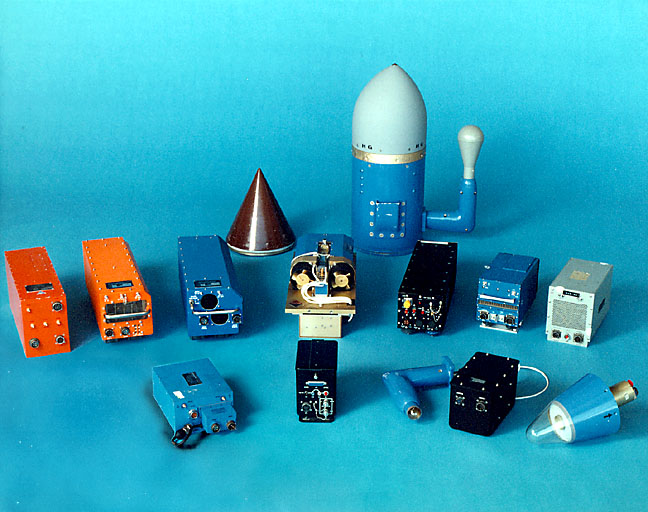
The current ULQ-21 CM Set consists of several interchangeable modules. Its modularity allows for configuration versatility and flexibility to meet many different mission, application, and installation requirements.
Through numerous transmitter and antenna configurations, the ULQ-21 allows versatile power and gain variations and spatial coverage. One unique antena configuration is the special transmit antenna. Consequently, by using combinations of the described modules, the ULQ-21 CM Set can be tailored to fit specific needs.
The number of ULQ-21 modules continuously increases with ongoing system development. Currently, the ATST is developing miniaturized payloads for smaller aerial targets such as the BQM-74. These efforts include the development of an advanced noise generator, IFM noise alternative, advanced VDA, miniature RGS box/receiver, and miniature PM controller.
CONFIGURATIONS
| Operating Band | I | I | I | I | I | I | I | I | I | G/H | G/H | G/H | E/F | E/F | E/F | J | J | J | C/D | C/D | C/D | ||
|---|---|---|---|---|---|---|---|---|---|---|---|---|---|---|---|---|---|---|---|---|---|---|---|
| WCO | X | X | X | X | X | X | X | X | X | X | X | X | X | X | X | X | X | X | X | X | |||
| VDA | X | X | X | X | X | X | X | ||||||||||||||||
| MM | X | X | X | X | X | X | X | ||||||||||||||||
| PM | X | ||||||||||||||||||||||
| WG | X | X | X | X | X | X | X | X | X | X | X | ||||||||||||
| STA | X | X | X | ||||||||||||||||||||
| RT | X | ||||||||||||||||||||||
| MTDA | X | X | X | X | X | X | X | X | X | X | |||||||||||||
| SSA | X | ||||||||||||||||||||||
| 100W TWTA | X | X | X | X | X | X | X | X | X | X | X | X | X | X | X | X | X | X | X | X | X | ||
| MPM |
Selected combinations of the individual modules determine the parameters and characteristics of the ECM technique. The ability to add and remove these modules makes it possible for the ULQ-21 to effectively meet the broad spectrum of threat requirements in the ECM environment. This modular design also provides an economic advantage by using only those components required for a particular installation and specific threats. Finally, the ULQ-21's versatility and simplicity permit easy adaptation to any follow-on development with a minimum impact on system configuration and logistics support.
ULQ-21 In Pod Tray Configuration
The noise techniques attempt to mask the illuminating radar's return signal with a larger power signal. These techniques utilize the internal noise source to generate the RF signal. The deception and transponder techniques attempt to provide false information (range, angle, or velocity) to the weapon system in order to degrade or break the weapon system or missile track. The resultant signal is then amplified to produce a larger signal to the radar than the actual radar return.
Although most modules are capable of stand-alone operation, they can also be used together to form unique ECM techniques. Particular technique characteristics or capabilities of one module combined with those of another module will determine the parameters and characteristics of the unique ECM technique. In addition, when the modules are used in the overall system and combined with antenna-based techniques, it can result in over 9,000 possible mode/technique combinations.
| WCO Modes | VDA Modes | RR/MM Modes | Antennas |
|---|---|---|---|
| BN | DN | SP | TB |
| CN | RD | ASN | CP |
| FTG | BDN | MFT | HOR |
| MFR | MFR | PLD | VER |
| RGS | VGS | STBY | SXP |
| STBY | RPTR | RGS SP | |
| RPTR | STBY | VGS SP | |
| NSAM | NBRN | RGS MFT | |
| SWPT | HO&H | RGS PLD | |
| RSAM | RSAM | VGS MFT | |
| RGS & SAM | RCDB | VGS PLD | |
| FTG & SAM | VGS & SAM | RGS & VGS PLD | |
| FTG & SAMH | VGS & RGS SP | ||
| RGS & SAMH | RGS & VGS MFT |
| ASN | Automatic Spot Noise | MFT | Multiple False Targets | SAM | Swept Amplitude Modulation |
|---|---|---|---|---|---|
| BDN | Blinking Doppler Noise | NBRN | Narrow Band Repeater Noise | SAMH | SAM Hold |
| BN | Blinking Noise | NSAM | Noise with SAM | SP | Stretched Pulse |
| CN | Continuous Noise | PLD | Pipeline Delay | STBY | Standby |
| CP | Circular Polarized | RCDB | Repeater Countdown Blink | SWPT | Swept Noise |
| DN | Doppler Noise | RD | Random Doppler | SX | Swept Cross Polarization |
| FTG | False Target Generator | RGS | Range Gate Stealer | TB | Terrain Bounce |
| HO&H | Hold Out & Hook | RPTR | Repeater | VER | Vertical Polarization |
| HOR | Horizontal Polarization | RSAM | Repeater with SAM | VGS | Velocity Gate Stealer |
| MFR | Multiple Frequency Repeater |
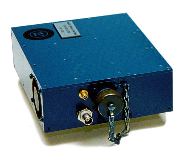
A unique member of the AN/ULQ-21(V) product line is the telemetry (TM) transmitter. It is a tunable S-Band frequency modulation transmitter that is primarily used to send data from airborne AN/ALQ-167(V) Electronic Countermeasures (ECM) pods to ground stations for analysis. It provides real-time TM data from the pods during training and live-firing missions. The transmitted information is used during flight missions to determine the operating conditions of the pods and the accuracy of various parameters. Because the transmitter is tunable, it can be used in missions that require the use of ore than one pod (i.e., missions that require multiple TM frequencies).
ULQ-21 Telemetry Transmitter
The ALT-41 CM Transmitter is used in the ALQ-167 to transmit RF signals during noise jamming modes of operation. The ALT-41 CM Transmitter transmits at 425 to 445 MHz.
The waveform generator (WG) is a video signal generator. It provides a stable timing signal to synchronize the blinking of two different ECM systems on separate platforms at frequencies between 0.006 and 50 Hz and a duty cycle of 50 percent.
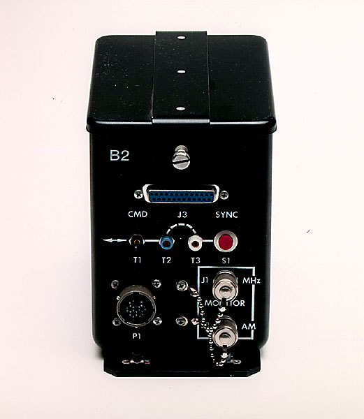
The polarization modulator (PM) provides nonadaptive swept cross polarization angle jamming techniques. The modulator, consisting of a PM controller and a transmit antenna, provides an output sweep time of 0.1 to 2.0 Hz and a sweep angle of ± 2° to ± 45°. The PM generates one of three polarization modes to the PM antenna which is simultaneously receiving the selected ECM technique output of the WCO via the 100 W TWTA. The three polarization modes are fixed vertical, fixed horizontal, and swept horizontal.
Polarization Modulator
The 100 W continuous wave traveling wave tube amplifier (TWTA) provides the final high power amplification of the ULQ-21 ECM signal before transmission.
The microwave power module (MPM) is the result of an effort to miniaturize the most common module, the I/J-Band TWTA. The MPM is a hybrid amplifier that utilizes the strong points of both solid-state and vacuum technology to provide the final stage power amplification. The MPM is currently planned to be used with the smaller subscale targets like the BQM-74 and the MQM-107. The I-Band MPM increases the smaller targets' I-Band RF power from 2 W to 100 W. Development of an E/F-Band MPM will begin in FY-96.
The 2 W solid-state RF amplifier (SSA) is used in place of the 100 W TWTA when a lower output power is required due to prime power or space limitations. The SSA produces the necessary gain and RF power needed to provide a deception jamming capability for smaller subscale targets.
2-Watt Solid-State RF Amplifier
The memory modulator (MM) has the capability to receive a coherent or noncoherent radar signal, store the signal, and accurately reproduce the RF signal. The techniques generated by the I/J-Band MM include both RGS and coordinated velocity gate stealer in addition to range false targets and stretched pulse techniques. The E/F-Band MM generates only RGS techniques.
As a programmable set-on radar receiver/transmitter (RT), the RT is designed for a minimum measurement and set-on time. Although useful against all types of I-band radars, its primary function is to operate against frequency agile radars. It is designed for operation in the 9.0 to 10.4 GHz range, with a maximum sensitivity of -55 dBm. Its key feature is a set-on time of less than 250 ns. In addition, it has the ability to sort multiple radars on the basis of RF frequency and pulse repetition interval using a programmable RF library. The RT can be incorporated into the ULQ-21 system, or it can be used as a stand-alone device for specialized applications and laboratory testing.
Set-On Radar Receiver/Transmitter
The velocity deception amplifier (VDA) provides the preamplification for the noise and deception modes and generates deception and AM techniques. The amplifier provides the preamplification needed to deliver the required RF level to the 100 watt (W) traveling wave tube amplifier (TWTA) so that sufficient output power and gain are attained.
Velocity Deception Amplifier
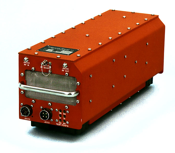
The multiple technique deception amplifier (MTDA) is a multiple channel, computer-controlled ECM technique generator. The amplifier is capable of combining three independent RF signals into a single ECM output. In addition, the amplifier is capable of applying multiple ECM modulations including frequency, phase, and AM to all three channels. The amplifier covers the 850 MHz to 18 GHz frequency region in three bands. This unit will be utilized in both full-scale and subscale aerial targets, as well as on manned aircraft.
Multiple Technique Deception Amplifier
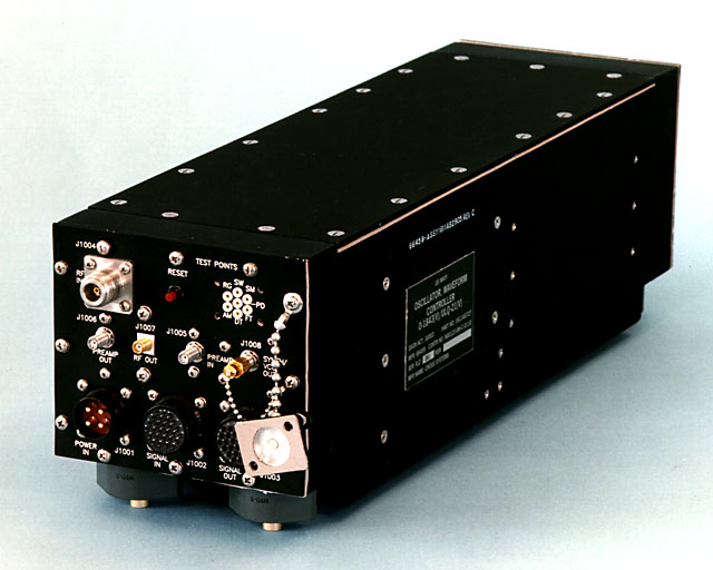
The waveform-controller oscillator (WCO) is fully programmable and controls up to three ULQ-21 modules at a time. It produces amplitude modulation (AM) and noise techniques and is used to detect incoming radio frequency (RF) pulses for the internally generated transponder range gate stealer (RGS)/false target techniques. After RF detection, the WCO generates either a fixed or a variable amount of delay and retransmits a pulse of noise (false target). The WCO can contain either an RF synthesizer (Type III, 9.0 to 10.5 GHz), a voltage controlled oscillator (VCO) (5 types, 1 to 18 GHz), or a triple VCO (5 types, 1 to 18 GHz) as the RF source.
Waveform Controller Oscillator
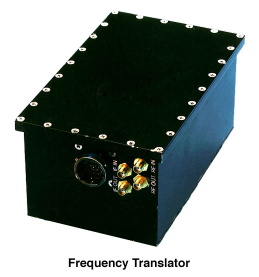
The frequency translator (FT) is capable of receiving all microwave signals throughout the weapon system frequency region (1 to 18 GHz). Once the FT receives the signal, it is translated into one of two narrow frequency bands to allow other ULQ-21 units (i.e., RT and MM) to receive the signal and operate in their existing frequency bands. Finally, the units return the signal to the FT where the signal is coherently translated back to the original frequency band for retransmission.
The noise generator is a bench adjustable microwave noise source. The generator can operate in frequency bands from 1 to 18 GHz; the frequency band is determined by the voltage controlled oscillator installed. The noise generator has seven remotely selectable modes: standby, noise spot, barrage noise, frequency comb, swept noise spot, swept barrage noise, swept frequency comb. The generator is temperature compensated and is designed for use in small drones; the power requirement is less than 9 watts from a 28 VDC power source.
There are two types of cross polarization techniques used, adaptive and nonadaptive. The new adaptive cross polarization system determines the polarization of the incoming signal and then retransmits the signal with an orthogonal (cross) polarization. Adaptive cross polarization is an improvement over nonadaptive since nonadaptive systems can only assume the polarization of the incoming signal and then retransmit a signal that is swept about the orthogonal of the assumed polarization.
The integration of the Ka-Band modules with proven ULQ-21 I-Band modules provides Ka-Band threat simulation without the need to develop specific Ka-Band ECM equipment. A key element required for Ka-Band threat simulation is the up/down converter. This converter is capable of converting Ka-Band signals down to the I-Band frequency range and converting a modulated I-Band signal up to the original Ka-Band frequency range. Another module included in the Ka-Band system is the Ka-Band traveling wave tube amplifier. The Ka-Band system also includes a Ka-Band antenna. The ULQ-21 modules used with the Ka-Band modules are the WCO, RF synthesizer, VDA, and WG. The complete Ka-Band/ULQ-21 system has a maximum gain of 87 dB and an effective radiated power of 3.2 kW.
The linear low gain antenna group was designed to produce a minimum gain of 10 dB with an antenna beamwidth of 50 degrees. The linear high gain antenna group was designed to produce a minimum gain of 16 dB with an antenna beamwidth of 25 degrees.
