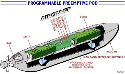
The AN/ALQ-99 Tactical Jamming System (TJS) onboard system includes the receiver, processor, and aircrew interfaces. The TJS also includes a selection of mission-configured jammer pods carried as external stores. Each jammer pod contains a ram air turbine generator, two selectable transmitter modules with associated antennas, and a universal exciter which is interfaced with and controlled by the onboard system and aircrew. The modular open architecture of the jammer system, which facilitates optimizing transmitters and antennas for a given frequency range, also facilitates tailored mission configurations.
The AN/ALQ-99(V) Receiver Processor Group (RPG) system was developed for use in the severe interference environment of the EA-6B jamming aircraft. The RPG had completed Operational Assessment and obtained a recommendation for production before program cancellation in 1993. Six RPG EDM systems were delivered. The AN/ALQ-99 RPG provided precision direction finding, passive ranging, identification, and threat warning, and was intended for the Navy EA-6B ADVCAP aircraft in very dense environments and in the presence of onboard jamming. This system included look-through, look-above, and look-around techniques to control the interference, as well as processing algorithms to contend with the resulting fragmented pulse data. The RPG performed surveillance, radar warning, and countermeasures management in support of standoff and escort jamming missions. The system uses four quadrants of AZ/EL interferometer arrays for full azimuth coverage precision monopulse DF measurement. The receiver is a narrowband channelizer cued receiver architecture with a wide instantaneous bandwidth and multiple cued narrowband channels for simultaneous pulse measurement capability. The RPG performed real time lookthrough control of the ALQ-99 jammers to accomplish all required threat emitter detection and measurement functions without degrading jammer effectiveness. To achieve this, data processing algorithms were developed with lookthrough samples providing as little as 1% of an emitter's pulses. The current EA-6B upgrade program includes the Universal Exciter Upgrade (UEU), the Band 9/10 Transmitter (transferred to the Navy from the canceled EF-111 SIP), and the Low Band Transmitter (LBT), all of which are modular upgrades for use with the AN/ALQ-99 jamming pods. Marconi Aerospace Electrical Systems of Rockville MD delivered the first ALQ-99 Band 9/10 radar jamming transmitter for the EA-6B Prowler on 08 April 1999. This initial delivery was the first of 120 planned units, which will provide new jamming capabilities to counter advanced surface-to-air missile systems.The Band 9/10 Transmitter [XMTR] is intended to be capable of replacing existing Band 9 transmitter modules in the TJS configurable architecture, while extending the transmit frequency coverage through all of the system defined Band 9 and Band 10. This design provides the extended frequency coverage with the added operational flexibility of not requiring separate Band 9 and Band 10 modules for a missionized configuration which requires transmitter coverage in both bands. The Band 9/10 transmitter completed DT in June 1997 and the OPEVAL was conducted from July through August 1997 in accordance with the DOT&E approved Test Plan. MS-III is planned in 1QFY98. OPEVAL test flights were conducted by VX-9 at the Electronic Combat Range at Naval Air Warfare Center, Weapons Division, China Lake, CA, at the Air Force Material Command Nellis AFB Range complex, and during other VX-9 test flights. Fleet Navy and Marine Corps Prowlers carrying the comparison baseline Band 9 XMTR configuration also supported the OPEVAL. The VX-9 operational EA-6B aircraft was configured with both of the tested Band 9/10 XMTRs.
The FY97 OPEVAL of the ACAT-III Band 9/10 XMTR was adequate to find it effective. The Band 9/10 XMTR was assessed to be only potentially suitable due to an incompatibility under some conditions between the existing extended high band radome and transmissions in the Band 10 region. The Band 9/10 XMTR met its basic requirement for equivalent effectiveness to the current Band 9 transmitter in the frequency band covered by the current Band 9 transmitter. It also demonstrated effectiveness in the Band 9 /10 extended frequency range. Some scenarios tested demonstrated a definite requirement for follow-on tactics development to ensure effective employment. The two Band 9/10 transmitters tested were the newest of five EMD systems built, and were considered to be production representative after correction of hardware deficiencies discovered during DT, and after progressive overhaul with new components during the course of the extended DT. The systems under test performed without mission affecting failures throughout the OPEVAL. The one major compatibility problem with the existing radome must be resolved via FOT&E prior to fleet deployment. This condition was well documented prior to entering IOT&E. Band 10 spot dwell on some azimuths are currently limited in order to guard against possible charring or delamination of the radome material. An ongoing radome material upgrade is planned to be completed in parallel with production of the Band 9/10 transmitter modules. Due to the azimuths of concern and predominant tactics, this restriction has virtually no adverse operational impact. It is imposed to prevent inadvertent damage of the radome. The radome upgrade is apparently fully funded and assessed as a low technical risk. The Navy's stated plan is to conduct FOT&E to demonstrate resolution of the radome incompatibility prior to any fleet deployment of the Band 9/10 XMTR, in order to field the system without operator controlled azimuth restrictions. The Low Band Transmitter (LBT) is designed for 1-3 Band Coverage, with several types of azimuth coverages (omni, bi-directional, or sector). The LBT is designed to support communications jamming, and to be controlled via direct 1553 Bus Control. Operationally, the LBT is missionized by one of four Antenna assemblies (3 Horizontal & 1 Vertical): Horiz Low (coverage Freq Low (FL) to FL+80), Horiz Mid (FL+70 to FL+230), Horiz High (FL+205 to Freq High (FH)). The one vertical antenna can be operated in two sub-bands: Vertical Low (FL to FL+20), and Vert High (FL+15 TO FH). The frequency breaks between antennae are still to be firmly set by Tracor. For LBT antennae which can be in either an omni mode or a bi-directional mode, the current design calls for the Central Mission Computer (CMC) to automatically switch antenna modes to ensure that all threats are covered. Scenarios could be imagined (terrain masking, etc), where the operator might wish to select the antenna mode either in mission planning or manually. The operator should be able to specify by phase during mission planning whether he/she wants: 1) CMC auto control, 2) Bi-directional only, or 3) Omni only. Additionally, the operator should be able to interogate an assignment and change the antenna mode; mode will remain in effect until the altered assignment is cleared (either by phase if a phase PA, or by the operator if a DA, AA, or operator made PA).The LBT Jammer Footprint GEO Display for sector and bi-directional assignments has been prototyped. Due to the fact that the Display Computer (DC) is out of memory, the bi-directional jammer footprints are drawn by connecting the four 3db/Rdr Horizon points (two on either side of the aircraft). Because of this, the aircraft symbol is often located slightly off center of the resulting "butterfly like" jammer footprint on the display.
The newly repackaged system can be configured as a Single-Seat Basic System or as a Dual-Seat Enhanced System. Contained within a pod, the electronics within the ALQ-99 utilizes a pre-mission planning system. This allows the user to achieve high-jamming capability at a low cost.