


AN/FPS-115 PAVE PAWS Radar
PAVE PAWS is an Air Force Space Command radar system operated by 21st Space Wing squadrons for missile warning and space surveillance. A Request for Proposal was submitted to industry 13 June 1975 for PAVE PAWS, a long-range, phased-array radar system. Designed to detect and characterize a sea-launched ballistic missile attack against the United States, Air Force Rome Air Development Center [RADC] was responsible for the design, fabrication installation, integration test, and evaluation of the system.
PAVE is an Air Force program name, that, contrary to some reports, does not have an expansion, while
PAWS stands for Phased Array Warning System. The radar is used primarily to detect and track sea-launched and intercontinental ballistic missiles. The system also has a secondary mission of
Earth-orbiting satellite detection and tracking. Information received from the PAVE PAWS radar systems pertaining to SLBM/ICBM and satellite detection is forwarded to the United States Space Command's Missile Warning and Space Control Centers at Cheyenne Mountain Air Force Base, Colo. Data is also sent to the National Military Command Center and the US Strategic Command.
PAVE PAWS reached initial operating capability 4 April 1980 at Otis AFB in Massachusetts, and 15 August at Beale AFB, California. Beale AFB and Cape Cod AFS are the only two operating PAVE PAWS sites in the United States. There is a decommissioned PAVE PAWS radar site at Robins AFB, Georgia. This site was closed as a cost-saving measure at the end of the Cold War. There was a PAVE PAWS EWR at Eldorado AFS, Texas. This radar was dismantled and moved to Clear AFS, Alaska and is scheduled to be operational in 2001. Clear AFS, Alaska is a Ballistic Missile Early Warning System site that is scheduled to become a PAVE PAWS site in early 2001.
The radar system is capable of detecting and monitoring a great number of targets that would be
consistent with a massive SLBM attack. The system must rapidly discriminate between vehicle
types, calculating their launch and impact points in addition to the scheduling, data processing and
communications requirements. The operation is entirely automatic, requiring people only for
monitoring, maintenance and as a final check on the validity of warnings. Three different
computers communicating with each other form the heart of the system which relays the
information the Cheyenne Mountain Air Force Base.
The mission of the PAVE PAWS radar installations involves two activities. The first activity, surveillance, is to detect and determine attack characteristics of Intercontinental Ballistic Missiles and Sea Launched Ballistic Missiles that might penetrate the PAVE PAWS field of view. Once detected, the launched object is continuously tracked and its trajectory estimated. Any object that separates from a booster is also tracked as it approaches. The second activity, tracking, supports the USSPACECOM
Space Surveillance Network, which involves the surveillance and tracking of earth satellites and identification of other space objects.
To detect objects, the radar devotes approximately half of its capabilities to generate what is called a surveillance fence. This refers to scanning at elevations between 3 and 10 degrees above horizontal over 240 degrees (the azimuth) of a 360 degree circle with the radar at the center. In the
surveillance mode, the position of the beam changes within this surveillance space according to a programmed pattern, moving from one position to another within tens of microseconds. In the surveillance mode, both faces of the radar are simultaneously active. Under normal circumstances, 11 percent of the radar resource is devoted to surveillance activities. The radar is also capable of performing enhanced search where the duty cycle is increased to 18 percent with no tracking being performed.
To track objects, the radar can allocate the remainder of its capabilities to focus on particular objects or a small cluster of objects. Normally, this would take up about 7 percent of the available radar resource, for a combined surveillance and tracking duty cycle of 18 percent. This
means that on average the radar is transmitting pulses only 18 percent of the time. The maximum possible use of the radar resource for combined surveillance and tracking activities is 25 percent and is the
operating condition that produces the maximum possible power density.
Under very exceptional circumstances of heavy tracking assignment the duty cycle of either face can be increased to 25%; under those conditions the duty cycle of the other face is necessarily reduced to
11%. The proportion of time that the radar is allocated to each activity varies considerably. Each activity demands that different patterns of pulsed signals be transmitted by the radar that are affected by the size, trajectory, and distance of objects. Thus, as part of the existing PAVE PAWS mission there are differences between the number of pulses, their duration, and repetition frequency.
The unique aspect of this radar system is the phased array antenna technology. This system differs
from a mechanical radar which must be physically aimed at an object in space to tract or observe
it. The phased array antenna is a fixed position and is part of the exterior building wall. Phased
array antenna aiming, or beam steering, is done rapidly by electronically controlling the timing, or
phase, of the incoming and outgoing signals.
Controlling the phase through the many segments of the antenna system allows the beam to be
quickly projected in different directions. This greatly reduces the time necessary to change the
beam direction from one point to another, allowing almost simultaneous tracking of multiple targets
while maintaining the surveillance responsibility. The large fixed antenna array through its better
beam focusing, improves system sensitivity and tracking accuracy.
A phased array antenna, as any other directional antenna, will receive signals from space only in
the direction in which the beam is aimed. The maximum practical deflection on either side of
antenna center of the phased array beam is 60 degrees. This limits the coverage from a single
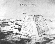
antenna face to 120 degrees. To provide surveillance across the horizon, the building housing the
entire system and supporting the antenna arrays is constructed in the shape of a triangle. The two
building faces supporting the arrays, each covering 120 degrees, will monitor 240 degrees of
azimuth.
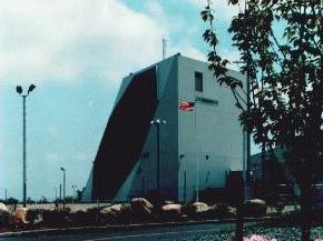
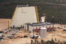
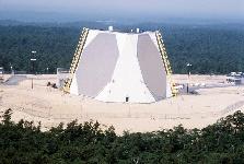
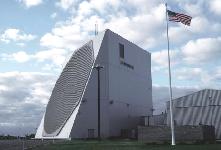
Each of the PAVE PAWS radars is housed in a 32-meter (105-foot) high building with three sides. Two flat arrays of individual radiating elements transmit and receive RF signals generated by the radar. The equipment that generates the RF signals and then analyzes the reflected signals is housed inside the radar building. The two array faces are 31 meters (102 feet) wide and are tilted back 20 degrees to allow for an elevation deflection from three to 85 degrees above the horizon. The lower limit provides receiver isolation from signals returned from ground clutter and for environmental microwave radiation hazard protection of the local area.
The active portion of the array resides in a circle 22.1 meters (72.5 feet) wide in the center of the array. Each radiating element is connected to a solid-state transmit/receive module that provides 325 watts of power and a low-noise receiver to amplify the returning radar signals. The RF signals transmitted from each array face form one narrow main beam with a width of 2.2 degrees.
The radar beam consists of a series of electromagnetic pulses, the characteristics of which (pulse length, frequency) would vary depending on mission requirements. The beam is directed at elevations between 3 and 85 degrees from horizontal, covering an azimuth of 120 degrees per face, for total coverage of 240 degrees. Software programming and redundant automatic interlocks combine to provide a triple-redundant system, which means that a simultaneous failure of three systems would be required to direct the beam outside the designated elevation and azimuth ranges.
Most of the energy (approximately 60 percent) is contained in the main beam. Smaller amounts of energy are emitted by the radar outside the main beam. These energy patterns are called sidelobes. By convention, sidelobes are given numbered designations with the lower numbers being closer to the main beam than the higher numbered ones. The energy contained in these sidelobes progressively decreases with distance from the main beam and from the radar. The first sidelobe is a concentric circle around the main beam. The second and higher sidelobes are narrow beams arranged around the main beam. Their shapes are similar to the main beam but have significantly lower power densities. The maximum power density of the first sidelobe is 1/100th (1 percent) of the maximum power density of the main beam. The maximum power density of the second sidelobe is only 1/1000th (0.1 percent) of the maximum power density of the main beam. The power density levels in the sidelobes quickly drop to insignificant levels as they progress away from the main beam. Since the main beam cannot be aimed lower than 3 degrees above a horizontal plane (see figure 1-3), it never intercepts the ground. Therefore, only the sidelobes intercept the ground. Additionally, the antenna beam is constantly scanning. As the beam scans away from a particular direction, sidelobes intersect the ground progressively further from the main beam. Thus, the higher numbered sidelobes, with significantly lower energy, intersect the ground. The result is that the vast majority of the energy emitted by the radar is directed upward where it is used to detect potential targets.
The far-field region begins at 439 meters (1,440 feet). The exclusion fence at Beale AFB and former exclusion fence at Cape Cod AFS are at approximately 305 meters (1,000 feet). Restricting the lowest elevation of the main beam to 3 degrees above horizontal prevents anyone on the ground or in buildings or residences from being exposed to RF from the main beam, even considering its 2.2 degree width. When the topography of the sites surrounding the radars is taken into account, the elevation of the main
beam is still substantially above ground level. For example, at the Cape Cod AFS, ground elevation is 82 meters (269 feet) and the center of the radar faces are 97.5 meters (320 feet) above sea level. For a variety of locations evaluated in the 1979 Cape Cod AFS EIS, the highest elevation within 11,125 meters (36,500 feet) of the radar was the road portion of the Sagamore Bridge at an 83.8-meter (275-foot) elevation. The bridge was identified as being 2,582 meters (8,470 feet) from the radar (Department of the Air Force, 1979). At this location, the center of the main beam would be 149 meters (489 feet) above the ground, and the bottom of the beam width would be 101 meters (331 feet) above the ground. At the most distant location studied, the Otis Schools, the center of the main beam would be 653 meters (2,142 feet) above the ground, and the bottom of the beam width would be 439 meters (1,440 feet) above the ground.
Specifications
|
|
Peak Power | 1,792 active elements at 325 watts = 582.4 kilowatts (kW)
|
| Duty Factor | 25% (11% search, 14% track)
|
| Average Power | 145.6 kW
|
| Effective Transmit Gain | 37.92 decibel (dB)
|
| Active Radar Diameter | 22.1 meters
|
| Frequency | 420 megahertz (MHz) to 450 MHz
|
| Radar Detection Range | 5,556 kilometers (3,000 nautical miles)
|
| Wavelength | 0.69 meters at 435 MHz
|
| Sidelobes | -20 dB (first), -30 dB (second),
-38 dB (root mean square)
|
| Face Tilt | 20 degrees
|
| Number of Faces | 2
|
| 3 dB Beam Width | 2.2 degrees
|


Sources and Methods
http://www.fas.org/spp/military/program/track/pavepaws.htm
Maintained by Robert Sherman
Originally created by John Pike
Updated Monday, March 06, 2000 6:48:39 AM