
Engineering Considerations for Gas Centrifuges
by Ivanka Barzashka and Ivan Oelrich

Establishing a domestic centrifuge program starts with developing technical expertise and acquiring or creating centrifuge engineering designs. Once this has been achieved, the construction phase includes obtaining the materials, manufacturing the centrifuge components, assembling and balancing the machines. The machines are then tested and accelerated up to their maximum operational speed. Once a centrifuge is running, the controllable variables of the machine (such as throughput and cut) have to be optimized to maximize its separative capacity. Ultimately, individual machines are piped together in cascades, which are designed for specific enrichment and throughput.
This article describes how centrifuges are built and how they are run. It discusses the engineering aspects of the main centrifuge components and stresses the challenges of building and operating the machines. First, the choice of material for the manufacture of centrifuge components is discussed. Then, we look at the major rotating components, the feed and extraction system, the casing and the power supply.
Materials for Building a Gas Centrifuge
The first challenge in developing a gas centrifuge program is obtaining the materials to manufacture the required parts. High strength, corrosion resistant material for the rotors, baffles, and bellows, as well as homogeneous magnets for top bearings may not be possible to manufacture domestically. However, proliferation-sensitive materials are included in a dual-use items list prepared by the International Atomic Energy Agency (IAEA) and their export to non-nuclear-weapon states is monitored [6].
Tensile strength and density are the most significant characteristic of the rotating centrifuge components and especially the rotor. The ultimate tensile strength characterizes the maximum stress that a material can endure before it ruptures. The ratio of the tensile strength σ to the density ρ of the material determines the maximum peripheral speed v of the rotor.
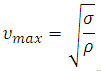
Note that the peripheral speed is not the rotational speed, but is the rotational frequency multiplied by the circumference of the rotor. A large radius and a low rotational speed can have the same peripheral speed as a small radius and a high rotational speed.
The elastic modulus, or the tendency to deform elastically under pressure, is a measurement of the material’s stiffness and closely correlates with the tensile strength. It is important in considering rotor material because it determines the flexural resonances of the rotating cylinder (discussed in more detail in the section below), which, in turn, determine the critical speeds of the rotor.
A centrifuge is required to spin continuously for long periods of time. Material properties such as creep and fatigue are considered to predict component and machine wear caused by periodic stress that is below the threshold to cause immediate failure.
The mass and stiffness of the material directly affect the centrifuge’s maximum speed. In turn, the overall separation performance is sensitive to maximum speed. Theoretically, the maximum degree of separation of the centrifuge is proportional to the peripheral speed raised to the fourth power. Thus, a 10 percent increase in the peripheral velocity would result in a 46 percent increase in maximum separation. In practice, engineering tradeoffs and inevitable inefficiencies in the machine make the increase substantially smaller, with some authors suggesting that separation proportional to the speed squared is a more reasonable approximation [8].

Early centrifuges used rotors made from high-strength aluminum alloys. More advanced designs use higher tensile strength materials with such as maraging steel, titanium, or glass or carbon fiber, resulting in significant increases in speed. Values range from 400 m/s for aluminum alloys, 440 m/s for titanium, 500 m/s for maraging steel, 522 m/s for glass fiber, and 720 m/s for carbon fiber. [3]
Since uranium hexafluoride (UF6) is a corrosive gas, the interior surfaces of the centrifuge need to be resistant to attack [2] and free of organic material, such as grease, hydrocarbon oil from bearings or even human fingerprint oil. This includes not only rotating components such as the rotor, but stationary ones such as feed and extraction piping.
Some materials are essentially inert to UF6 [15] because a thin film of metal fluoride forms, which protects the bulk of the material from further corrosion [16],[12]. According to the IAEA trigger list, stainless steel, aluminum, nickel and alloys containing more than 60 percent nickel are resistant to corrosion and are monitored. Copper and copper alloys such as bronze are also UF6 resistant [15], but are not the best choice for a centrifuge rotor due to relatively higher density.
Metals are sometimes anodidized, that is pre-oxidized, to improve corrosion resistance. This is usually done to maraging steel rotors using controlled atmosphere furnaces using a mixture of air and steam to control oxidation [14].
Constructing Centrifuge Components
Rotor
Constructing a centrifuge rotor that is perfectly balanced, that is, a rotor in which the geometric and mass axes coincide, is practically impossible. The difference between the two axes creates a rotating radial load – a net force that pulls the rotor laterally. Mass imbalance in a single plane can be detected when the rotor is at rest. Mass can also be out of balance at different points along the length of the rotor, creating forces that cause rocking of the rotor axis. This is called a dynamic unbalance because it cannot be detected without spinning the rotor. At high speeds, the unbalanced force can rock the rotor within its bearings, creating vibrations.

Unbalance forces can create synchronous whirls, which are rotations about the axis formed by the bearings occurring at the same frequency as the rotor rotation. The cylinder tries to rotate about its center of mass but is being pushed toward the axis defined by the bearings and their geometric center. There are two types of whirling in centrifuge rotors – cylindrical (or translatory [9]) and conical. The former is a horizontal displacement perpendicular to the axis of rotation and the latter is a tilt about the axis.
A rigid rotor has an effective mass and is supported by bearings, which provide a restoring force and act like springs. Any system with an inertial mass and restoring force or stiffness will have natural frequencies. When an external driving force appears, such as the unbalance force, and it has the same frequency as one of the natural frequencies, resonance is created. In centrifuges, these resonances are called critical speeds.
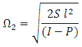
If we ignore the flexibility of the rotor and just consider the rotor mass and the stiffness of the bearings, these critical frequencies are called the rigid-body critical speeds. There are two types of rigid-body critical speeds due to the two types of whirls. The cylindrical and conical critical speeds are given respectively by the equations below, where S is the stiffness of the bearings, M is the mass of the rotor, l is the half bearing separation, I is the transverse inertia and P is the polar inertia [17].
![]()
Rotors can be meticulously balanced, which can greatly decrease the unbalance force but cannot eliminate it completely. Vibration can be mitigated by design of a flexible shaft-bearing system to allow the rotor to locate and freely spin around its center of gravity. Lowering the bearing stiffness also lowers the natural frequency making the resonance occur at a lower speed and reducing the total load because load is the displacement times the speed [17].
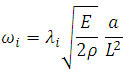
The ratio of the transverse to polar inertia increases with length and the conical critical speed is reduced, thus, for a longer rotor, traversing the rigid-body criticals becomes trivial [17]. However, a longer rotor encounters flexural critical speeds, which occur at higher frequencies. Whereas the rigid-body criticals depend on the vibrations within the bearings, the natural frequencies of flexure are due to longitudinal vibrations of the rotor itself (because we consider the bearings to be rigid), which depend on the modulus of elasticity E and the density of its material ρ. At certain speeds, the frequency of rotation equals the natural frequencies and resonance occurs. During resonance, the rotor will bend in the shape of the harmonics: for the first critical speed it will take the shape of an arc, for the second like an S and so forth. The critical flexural frequency ω is given by the equation below, where L is the length of the rotor, r is its radius, E is the modulus of elasticity and ρ is the density, λ is an eigenvalue and i is the mode number [3]:
![]()
There are two types of centrifuges: subcritical and supercritical. A rotor is subcritical when it operates at a rotational frequency less than the lowest flexural resonance frequency and supercritical when operates above it. The flexural critical conditions can be expressed in terms of the ratio between the rotor’s length and its radius. Therefore, knowing the dimensions of the rotor and its material properties, we can determine whether it is subcritical or supercritical. A rotor has many resonant frequencies and passing through each one creates a mechanical risk to the centrifuge. The goal is to maximize the separative capacity before hitting the next higher critical frequency, so centrifuges are usually designed to operate just below a critical frequency.
Traversing the flexural critical speeds is the major obstacle in getting supercritical centrifuges to rotate at their optimum speeds. There are three ways to do this: accelerate quickly through the critical speed, optimize the damping on the bearings, or insert bellows.
By quickly accelerating the rotor through the critical speeds, there will be no time for the amplitudes to reach destructive levels. This method was used with the Manhattan supercritical centrifuge at the University of Virginia in the 1940s. A powerful motor is required to drive the centrifuge rotor for this option. For industrial purposes, a more energy-efficient approach is to optimize the dampers, which is not a simple task. The problem of vibration damping was one of the reasons gas centrifuge were abandoned by the U.S. during the World War II Manhattan Project [17].
Bellows
Another way to help the supercritical centrifuge reach its maximum speed is to introduce bellows (or sylphons) along the length of the rotor. These are flexible joints that break up the rotor into several parts. Bellows have two benefits: they allow the rotor to bend and take up the shapes of the harmonics without breaking and they reduce the resonance frequencies, thereby decreasing the total force when the rotor passes through the critical speeds. Careful design and placement of the bellows allows management of the resonant frequencies. Bellows were first used in Soviet Union supercritical machines during the late 1940s and early 1950s [13].
Bearings

The purpose of bearings is to constrain a rotating object to spin about a specific position. Bearings behave like springs, since they apply a restoring force to set the rotating object back to its original position. The spring force constant or, in the case of bearings, the stiffness, is therefore an important parameter to consider. Two types of bearings were used for gas centrifuges. Hydrodynamic journal bearings were used in the Groth and Beams machines. This type of bearings is characterized by high stiffness and high power consumption. Zippe machines used a combination of a pivot and a magnetic bearing [3]. The magnetic bearing consisted of annular-shaped permanent magnets and was placed on the top of the centrifuge. It was used to relive the stress on the bottom bearing. Magnetic bearings have very little power loss and are suitable to work in a vacuum. This greatly reduces wear and energy consumption but also greatly lowers the stiffness of the bearing. Lower stiffness reduces the natural frequency, which diminishes the radial load caused by unbalancing. However, this also makes the centrifuge more delicate and susceptible to perturbations [17].
Extraction System: Scoops and Baffles
Material is extracted from inside the rotor by small stationary tubes called scoops. The scoops are located at the top and bottom of the rotor and fixed to the central gas extraction system. They extend out to the periphery of the rotor, since this is where most of the material is located due to the centrifugal forces created by the rapid spin. The scoop, which ends in a hook-shaped Pitot tube, faces the circulating gas and pressure is created, which pushes up the material. No extra power is required to move the gas to the next machine in a cascade because the scoops use the momentum of the rotating gas and the high pressure at the periphery. In a machine with thermally-driven circulation, the warm end scoop extracts the heavier material more abundant in U-238 and the cool-end scoop the lighter material richer in U-235. Sometimes scoops are shielded by baffles, so that no disturbance in the countercurrent is created. The baffles are rotating perforated discs, which separate the part of the rotor where separation takes place from the part of the rotor where the material is extracted. Unbaffled scoops can contribute to the countercurrent flow inside the machine, being the equivalent of heating. Aerodynamic properties of the scoops have an effect on the separation factor of the centrifuge and should be optimized for best performance. Scoops are made from corrosion resistant materials, but do not need to have the tensile strength of the rotor because they are stationary.
Vacuum Casing
 The outside surface of a modern centrifuge rotor is traveling well above the speed of sound so centrifuges are enclosed in a vacuum casing to minimize drag. The casing is also designed to contain an exploding rotor [2]. Operating the rotor in a vacuum also makes rotor temperature control easier, eliminating any unwanted convection in the gas in the rotor [16]. In addition, the casing isolates the machine from outside vibration, particularly from the other machines in the cascade.
Although the rotor shafts are sealed, it is possible for small amounts of UF6 to escape. A molecular pump is used to maintain the vacuum inside the centrifuge casing. Molecular pumps used in centrifuges are a type of drag pump. They consist of a smooth cylinder made of UF6 resistant material with spiral grooves, which is attached to the inside of the casing close to the rotor [6]. The movement of the rotor imparts a momentum to molecules that hit it and move them in the direction of rotation, or "drags" them along. The spiral grooves channel the molecules away from the low pressure end to the high pressure end. The most advanced type of drag pump is the Holweck pumps, which was what was used in the Zippe centrifuge [17].
Power Supply

The motor drive is operated in low voltage in high vacuum. The motor stators need to be especially designed for synchronous operation in vacuum. The frequency changers control the rotational speed of the rotors by supplying the rotor stators with power at the correct frequency. They need to have high stability, low harmonic distortion and high efficiency because they need to be able to successfully accelerate the rotors above critical speeds and avoid overheating in vacuum. Frequency changers convert the alternating current from the power grid to a higher frequency ranging from 600 Hz to 2000 Hz [6].
Ancillary Equipment
Ancillary, test, and production equipment such as such variable frequency power supplies for the drive motors, vacuum pumps, precision mass spectrometers or vibrational test systems can be obtained off-the-shelf. However, proliferation-sensitive materials, parts, and technology are included in IAEA's trigger list and their international trade is monitored.
Designing and building gas centrifuges pose significant engineering challenges. Some technological difficulties can be overcome in the laboratory but the solutions may prove to be uneconomic for large-scale production. For example, the United States developed prototype supercritical centrifuges but chose gaseous diffusion as the industrial method for uranium enrichment for its World War II Manhattan Project. Historically, the least time required to develop indigenous centrifuge technology has been 8 years, in the case of the Soviet Union. Even using acquired Urenco designs, it took Pakistan 6 years for the development of a centrifuge program, designed specifically for the production of bomb-grade uranium [18].
We would like to thank David Chichka, assistant professor of Mechanical and Aerospace Engineering at George Washington University, for his contribution and insights.
References
[1] Adams, M. L. (2000). Rotating Machinery Vibration: From Analysis to Troubleshooting . CRC.
[2] Avery, D. G., & Davies, E. (1973). Uranium enrichment by gas centrifuge. London: Mills and Boon.
[3] Benedict, M., Pigford, T. H., & Levi, H. W. (1981). Nuclear chemical engineering (2nd ed.). New York: McGraw-Hill.
[4] Callister, W. D. (2003). Materials Science and Engineering: An Introduction (6th ed.). New York: John Wiley & Sons, Inc.
[5] Den Hartog, J. P. (1985). Mechanical Vibrations (4th ed.). New York: Dover Publications.
[6] International Atomic Energy Agency. (2006, March 20). INFCIRC/254/Rev.8/Part 1a. Retrieved April 2, 2009, from http://www.iaea.org/Publications/Documents/Infcircs/2006/infcirc254r8p1.pdf
[7] Jousten, K. (2008). Handbook of Vacuum Technology (B. Nakhosteen, Trans.). Wiley-VCH.
[8] Kemp, R. S. (2009). Gas Centrifuge Theory and Development: A Review of U.S. Programs. Science and Global Security, 17(1).
[9] Rao, J. S. (1996). Rotor Dynamics (3rd ed.). New Age International.
[10] Redhead, P. A. (1997). Vacuum Science and Technology Pioneers of the 20th Century. New York: American Institute of Physics.
[11] Thomson, W. T., & Dahlen, M. D. (1998). Theory of Vibrations with Applications (5th ed.). Upper Saddle River, NJ: Prentice Hall.
[12] United States Enrichment Corporation. (1995, January). Uranium Hexafluoride: A Manual of Good Handling Practices (USEC-651, Revision 7). Retrieved April 2, 2009, from http://web.ead.anl.gov/uranium/guide/ucompound/propertiesu/uranium.cfm
[13] U.S., Central Intelligence Agency. (1957, October 8). The Problem of Uranium Isotope Separation by Means of Ultracentrifuge in the USSR (EG 1802). Retrieved April 2, 2009, from http://www.fas.org/irp/cia/product/zippe.pdf
[14] U.S. Department of Energy, Nuclear Transfer and Supplier Policy Division. (1996). Handbook for Notification of Exports to Iraq: Annex 3 (Vol. SARC - 001/98). Retrieved April 2, 2009, from http://www.iraqwatch.org/government/US/DOE/DOE-Annex3.htm
[15] U.S. Department of Energy. (1999, April). Final Programmatic Environmental Impact Statement for Alternative Strategies for the Long-Term Management and Use of Depleted Uranium Hexafluoride (DOE/EIS-0269), Appendix A: Chemical Forms and Properties of Uranium. Retrieved April 2, 2009, from http://web.ead.anl.gov/uranium/pdf/app_a.pdf
[16] Villani, S. (1976). Isotope Separation. American Nuclear Society.
[17] Whitley, S. (1984). Review of the gas centrifuge until 1962. Part II: Principles of high-speed rotation. Reviews of Modern Physics, 56(1), 67-97.
[18] Zentner, M. D., Coles, G. L., & Talbert, R. J. (2005). Nuclear Proliferation Technology Trends Analysis (Tech. No. PNNL-14480). Pacific Northwest National Laboratory.