

DOCUMENT 316-98
RANGE SAFETY GROUP
LASER RANGE SAFETY
WHITE SANDS MISSILE RANGE
KWAJALEIN MISSILE RANGE
YUMA PROVING GROUND
DUGWAY PROVING GROUND
ABERDEEN TEST CENTER
NATIONAL TRAINING CENTER
ATLANTIC FLEET WEAPONS TRAINING FACILITY
NAVAL AIR WARFARE CENTER WEAPONS DIVISON
NAVAL AIR WARFARE CENTER AIRCRAFT DIVISION
NAVAL UNDERSEA WARFARE CENTER DIVISION, NEWPORT
PACIFIC MISSILE RANGE FACILITY
NAVAL UNDERSEA WARFARE CENTER DIVISION, KEYPORT
30TH SPACE WING
45TH SPACE WING
AIR FORCE FLIGHT TEST CENTER
AIR FORCE DEVELOPMENT TEST CENTER
AIR WARFARE CENTER
ARNOLD ENGINEERING DEVELOPMENT CENTER
GOLDWATER RANGE
UTAH TEST AND TRAINING RANGE
DISTRIBUTION A: APPROVED FOR PUBLIC RELEASE;
DISTRIBUTION IS UNLIMITED
DOCUMENT 316-98
LASER RANGE SAFETY
OCTOBER 1998
Prepared by
Range Safety Group
Laser Safety Committee
Range Commanders Council
Published by
Secretariat
Range Commanders Council
White Sands Missile Range
New Mexico 88002-5110
TABLE OF CONTENTS
PAGE
CHAPTER 1 – GENERAL *
1.1 Scope *
1.2 Application *
1.3 Exclusions *
1.4 High Energy Systems *
1.5 Broad Beam Lasers *
1.6 Force-On-Force Exercises *
1.7 Content 1-3
CHAPTER 2 - APPLICABLE DOCUMENTS *
2.1 General *
2.2 Government Documents *
2.2.1 Standards *
2.2.2 Other Government Publications. *
2.3 Non-Goverment Publications *
2.4 Order of Precedence *
CHAPTER 3 - DEFINITIONS *
CHAPTER 4 - GENERAL RANGE CONTROL PHILOSOPHY *
4.1 General Policy *
4.2 Recommended Targets 4-3
4.3 Beam Control *
4.4 Specular Reflectors *
4.5 Hazards. *
4.6 Unprotected Personnel *
4.7 Warning Signs *
4.8 Personnel Protection *
4.9 Magnifying Optics *
4.10 Night Vision Goggles/Devices *
4.11 Specific Guidelines *
4.12 Laser Pre-firing and Post-firing Restrictions *
4.13 Stationary Continuously Operating Lasers *
4.14 Tactics *
4.14.1 Ground Laser Designators *
4.14.2 Airborne Wingman Laser *
PAGE
APPENDIXES
APPENDIX A - LASER SAFETY INFORMATION FOR FIRE CONTROL LASER
SYSTEMS A-1
1.0 Scope A-2
2.0 Fire Control Laser Safety Features A-2
2.1 Ruby LRFs.. A-2
2.2 Distance S. A-2
2.3 Current Laser Safety Summary.. A-2
2.4 Buffer Zones. A-12
2.5 Eye Protection. A-12
2.6 Fielded Laser System Descriptions. A-12
2.7 Inactive Lasers Descriptions and Associated Systems A-15
APPENDIX B - MULTIPLE INTEGRATED LASER ENGAGEMENT SYSTEM
(MILES) OPTICAL SAFETY SUMMARY B-1
1.0 Scope B-2
2.0 Applicable Documents B-2
3.0 Miles B-2
4.0 Schwartz Electro-Optic Controller Gun B-2
APPENDIX C - AIR TO GROUND ENGAGEMENT SYSTEM/AIR DEFENSE,
LASER AIR TO AIR GUNNERY SYSTEMS, PRECISION GUNNERY TRAINING
SYSTEM, AND AN/GTV-1 SAFETY SUMMARY C-1
1.0 Scope C-2
2.0 Applicable Documents C-2
3.0 Safety Summary C-2
APPENDIX D - SAMPLE CONTENT FOR LASER SAFETY SOP FOR
TRAINING WITH PORTABLE FIRE CONTROL LASERS D-1
1.0 Scope D-2
2.0 Warning D-2
APPENDIX E- EQUATIONS FOR LASER HAZARD EVALUATION E-1
1.0 Scope E-2
2.0 Applicable Documents E-2
3.0 Equation Applications E-2
3.1 Sloping Ranges.. E-2
3.2 Shipboard Laser System.. E-2
3.3 Hazard Evaluation.. E-3
3.3.1 Buffered Footprint Definition. E-3
3.3.2 Hazard Evaluation Without Specular Reflections. E-3
3.3.2.1 Single Laser Aircraft Heading. E-3
3.3.2.2 Multiple Laser Aircraft Headings E-3
3.3.2.3 Level Ground Examples. E-3
3.3.2.3.1 Example 1 (Level Ground). E-3
3.3.2.3.2 Example 2 (Level Ground). E-11
3.3.2.4 Unlevel Terrain. E-11
3.3.2.4.1 Target on Rising Terrain Or Hills Behind Target E-11
3.3.2.4.2 Falling Terrain in Target Area or Hills in Foreground E-11
3.3.2.4.2.1 Foreground Distances. E-11
3.3.2.4.2.1 Distance Beyond Target . E-11
3.3.3 Specular Reflections E-11
3.3.4 Aircrew E-14
3.3.5 Ground Personnel, Shipboard Personnel, Other Aircraft, and Surrounding
Community. E-14
3.3.6 Hazard Distances From Various Reflective Surfaces E-14
3.4 Footprint Determinations E-14
3.4.1 Ground Based Lasers. E-14
3.4.1.1 Vertical Buffer Far Boundary E-14
3.4.1.2 Vertical Buffer Near Boundary E-18
3.4.1.3 Horizontal Buffer E-18
3.4.2 Airborne Laser with Target on Level Ground E-19
3.4.2.1 Aircraft Minimum Altitude E-19
3.4.2.2 Left and Right Hand LSDZ E-22
3.4.2.3 Airborne Laser with Target on Sloping Ground E-22
3.4.2.3.1 Buffered Footprint E-22
3.4.2.3.2 For Far Target E-25
3.4.2.3.3 For Near Target E-25
3.4.2.3.4 Left and Right Hand LSDZ E-25
APPENDIX F - DOD LASER RANGE SURVEY CHECKLISTS F-1
1.0 Scope F-2
2.0 Checklists F-2
APPENDIX G - SPECULAR REFLECTION G-1
1.0 Scope G-2
2.0 Applicable Documents G-2
3.0 Specular Reflection Characteristics G-2
3.1 Flat Reflectors G-2
3.2 Hazardous Ranges of Reflected Laser Beam G-2
3.2.1 Reflection from Reflector Larger Than Cross Section of Incident
Laser Beam G-3
3.2.2 Reflection from Reflector Smaller than Incident Laser Beam Cross
Section G-8
APPENDIX H - SEPARATE TARGET (SEPTAR) AND SHIP’S TOWED TARGET OPERATIONS H-2
1.0 Scope H-2
2.0 Applicable Documents H-2
3.0 Septar Operations H-2
4.0 Ship's Towed Target Operations H-9
APPENDIX I - SATELLITE SAFETY PROCEDURES I-1
1.0 Scope I-2
2.0 References I-2
3.0 Definitions For Space-Directed Laser Emissions I-2
4.0 Applicability I-4
5.0 Concept Of Operations 1-4
6.0 JCCDOA Responsibilities I-5
7.0 Laser Facility Responsibilities I-6
FIGURES PAGE
4-1 Direct intrabeam viewing 4-2
4-2 Reflected intrabeam viewing 4-2
4-3 Example: warning sign 4-5
4-4 Sample safety exclusion cone for ground laser designator 4-12
4-5 Sample side view of safety exclusion volumes for ground laser
designator 4-14
designator aircraft during continuous laser designation 4-14
4-7 Sample vertical view of safety exclusion cones to prevent homing on
continuous laser designator aircraft 4-15
4-8 Sample delayed laser designation safety exclusion cone, vertical view 4-16
4-9 Generalized concept of risk variables related to laser target designator
and laser seeker field of view 4-17
6-1 Diffuse reflection and specular reflection 6-2
6-2 Laser surface danger zone (SDZ) 6-8
6-3 LSDZ without and with natural backstop 6-9
6-4 Example laser range danger fan/laser surface danger zone 6-11
6-5 Vertical buffer zone 6-12
6-6 Effects of backstops 6-13
6-7 Example of airborne beam reflection 6-15
6-8 Examples of the use of natural backstops, buffer zones, and restricted
air space 6-19
6-9 Supervised laser demonstration for military training. (modified from
FIGURE 2D, ANSI Z136.1) 6-22
E-1 Laser footprint with single target - side view E-4
E-2 Laser footprint with multiple targets - side view E-4
E-3 Laser footprint top view E-4
E-4 LSDZ - attack bearing 90o E-10
E-5 LSDZ - attack bearing 70 to 110o E-10
E-6 LSDZ - attack from any direction E-10
E-7 LSDZ with rising terrain E-12
E-8 Use of natural backstops to control laser beam E-12
E-9 Insufficient backstop to control laser beam E-12
E-10 LSDZ with terrain sloping down. Range less than NOHD E-13
E-11 LSDZ with terrain sloping down. Range greater than NOHD E-13
E-12 Reflections from still water with LDZ E-13
E-13 Example of airborne laser beam reflection E-15
E-14 Potential exposure modes E-16
E-15 Reflections from flat specular surface - side view E-16
E-16 Reflections from flat specular surface - top view E-16
E-17 Vertical buffer and LSDZ geometry E-17
E-18 Alculation of available buffer versus allowed buffer E-20
E-19 Airborne laser buffer geometry - level ground E-21
E-20 Example laser aircraft flight profile E-23
E-21 Laser target on sloping terrain E-24
G-1 LSDZ with specular reflections from standing still water G-5
G-2 LSDZ with specular reflective target - side view G-5
G-3 Specular reflectance from both surfaces of plate glass (index of
refraction = 1.5) G-6
G-4 Specular reflectance from sea water (index of refraction = 1.378) G-7
G-5 Specular reflectance from fresh water (index of refraction =1.33) G-8
H-1 SEPTAR operations area and buffer zone H-3
H-2 Zones relative to towing ship's heading in which laser operations are
permitted for A-6E TRAM, OV-10D NOS, F111-Pave Tack, and
Pave Spike H-10
TABLES PAGE
6-1 Typical reflective surfaces 6-3
A-1 NOHD and range safety information for fielded military laser systems A-3
A-2 NOHD and range safety information for commercial off-the-shelf
(COTS) military lasers A-8
A-3 Eye protection requirements for fielded lasers A-9
A-4 Eye protection requirements for COTS military lasers A-11
B-1 NOHD for miles and other training lasers B-3
C-1 Cautionary distances for eye exposure to the AGES/AD, LATAGS,
PGTS, TWGSS/PGS, JAVELIN, ISMT/IST, and AN/GVT-1 C-4
E-1 Laser footprint table for: pave spike (using vacuum NOHD) E-5
E-2 Laser footprint table for: pave spike (including atmospheric attenuation
for lasing from altitudes below 1 km MSL only) E-6
E-3 Laser footprint table for: pave tack (using vacuum NOHD) E-7
E-4 Laser footprint table for: pave tack (including atmospheric attenuation
for lasing from altitudes below 1 km MSL only) E-8
E-5 Laser footprint table for: any laser system with beam divergence
0.5 MRAD E-9
G-1 Reflectivity of glass at various angles of incidence G-10
G-2 Reflectivity of fresh water at various angles of incidence G-10
G-3 Reflectivity of sea water at various angles of incidence G-11
G-4 Reflectivity of shiny metal G-11
H-1 Flight profile against SEPTAR. One NMI buffer zone around
one nautical mile operation area - 0 degree to 360 degrees H-4
H-2 Flight profile against SEPTAR. Two NMI buffer zone around
one nautical mile operation area - 0 degree to 360 degrees H-5
H-3 Flight profile against SEPTAR. Three NMI buffer zone around
one nautical mile operation area - 0 degree to 360 degrees H-6
H-4 Flight profile against SEPTAR. Four NMI buffer zone around
one nautical mile operation area - 0 degree to 360 degrees H-7
H-5 Flight profile against SEPTAR. Five NMI buffer zone around
one nautical mile operation area - 0 to 360o H-8
FOREWORD
This document, Laser Range Safety, is published with the approval of the Range Commanders Council. The contents of this handbook are intended to serve as a guide to the safe use of lasers and laser systems used on military reservations and in military controlled areas. This edition of the 316 has been extensively revised from the previous issue.
Subject term (keyword) listing
Apertures Hazard Zone Laser Radiation Transmittance
Attenuation Lasers Optical Density Ultraviolet Radiation
Exclusion Zones Laser Radiation Radiant Energy Wavelength
This document is applicable to all Department of Defense (DOD) member ranges, operational test facilities where lasers are used, and all DOD laser operations conducted on non-DOD controlled ranges or test facilities. The guidance in this document does not replace other procedures or release individuals from compliance with the requirements of their particular service.
Certain provisions of this handbook are the subject of international standardization agreement, STANAG 3606, Evaluation and Control of Laser Hazards. When any amendment, revision, or cancellation of this handbook is proposed which is inconsistent with the international agreement concerned, the preparing activity will take appropriate action through international standardization channels, including departmental standardization offices, to change the agreement or make other appropriate accommodations.
A companion document, issued under the authority of DOD, is DOD Instruction 6055, Personnel Protection Policy Exposure to Laser Radiation. Its purpose is to provide uniform guidance for the safe use of military lasers and laser systems on DOD military reservations or military controlled areas worldwide. Copies of this document may be obtained through DOD publication channels. Other federal agencies and the public may obtain copies from:
Office of the Assistant Secretary of Defense
Environment and Safety
Washington, DC 203330-1000
Copies of Laser Range Safety may be obtained from the
Secretariat
Range Commanders Council
ATTN: STEWS-RCC
White Sands Missile Range, New Mexico 88002-5110
The Range Commanders Council point of contact is
Naval Air Warfare Center Weapons Division
Code 870000E Mr. George Wadley
Point Mugu, California 93042
DSN 351-0041
Commercial (805) 989-0041
GENERAL
This handbook provides uniform evaluation guidance for the safe use of military lasers and laser systems on worldwide Range Commanders Council (RCC) military reservations or military controlled areas. Each military service has previously established normal procedures for approving laser ranges. This guidance is intended to supplement these procedures. It does not replace those procedures or release individuals from compliance with the requirements of their particular service. The authority for guidance is the Laser System Safety Working Group (LSSWG) established by DODI 5000.1 and Range Commanders Council. Guidance for lasers not addressed here should be obtained from the LSSWG through respective service health and safety organizations listed in Paragraph 1.2.
1.2 Application
This handbook applies to:
US Army Center for Health Promotion and Preventive Medicine
ATTN: MCHB-DC-OLO
Aberdeen Proving Ground, Maryland 21010-5422
DSN 584-3932/2331, Commercial (301) 671-3932
Space and Naval Warfare Systems Command (Code 00F)
2451 Crystal Drive
Arlington, Virginia 22245-5200
DSN 332-7235/73, Commercial (703) 602-7235
Armstrong Laboratory
Health Physics
Optical Radiation Division
Brooks AFB, Texas 78235-5501
DSN 240-4784, Commercial (210) 536-3625
1.3 Exclusions
This handbook does not apply to indoor use, for example, laboratory laser repair depots or industrial laser facilities because of the unique control measures required, industrial and construction lasers such as those used for surveying; and new technology laser applications.
1.4 High Energy Systems
High energy laser systems (lasers capable of cutting material or burning standard target material) require unique control measures. Use of these lasers must be approved by the local Laser Safety Officer (LSO) in coordination with the specialists designated in paragraph 1.2.
1.5 Broad Beam Lasers
Lasers with broad beam or autonomous scanning systems that are not directly under the operator's control may require additional evaluation assistance from the organizations listed in paragraph 1.2.
1.6 Force-On-Force Exercises
Force-on-force exercises using lasers and laser devices are special cases requiring additional controls. Exceptions are training lasers such as the Multiple Integrated Laser Engagement System (MILES) which is addressed in Appendix B. These force-on-force lasers must be addressed on an individual basis by the local LSO with assistance from the service component safety and health specialist designated in paragraph 1.2.
This handbook contains appendixes, which give general and detailed policies to be followed in evaluating and recommending laser range safety procedures. Appendix A provides safety hazard control data for specific laser systems evaluated by each of the service safety specialists. Appendix B furnishes safety information on lasers used for scoring tactical exercises. Appendix C summarizes safety data for gunnery training systems and simulators. Appendix D is a sample of a laser safety standard operating procedure (SOP). Appendix E describes the equations used to determine Laser Surface Danger Zones (LSDZ)/Nominal Hazard Zones (NHZ). Appendix F contains checklists to be used for the laser safety pre-survey, the site survey, and the laser range safety evaluation reports. Appendix G discusses methods for evaluating hazards from specular reflections of the laser beam. Appendix H deals with safety policy for at-sea operations against ship towed targets and separate targets (SEPTAR). Appendix I addresses procedures for obtaining approval from the Space Command Control Center for Space Directed Emissions.
The documents listed below are referenced in Chapters 3, 4, and 5 of this standard. This list does not include documents cited in other sections of this document or recommended for additional information or as examples. While every effort has been made to ensure the completeness of this list, document users are cautioned that they must meet all specified requirements of the documents cited in Chapters 3, 4, and 5, whether or not they are listed below.
MILITARY STANDARDS
MIL-STD-1425A Safety Design Requirements For Military Lasers
And Associated Support Equipment
NATO STANDARDIZATION AGREEMENTS
STANAG 3606 Evaluation and Control of Laser Hazards
Unless otherwise indicated, copies of the above standards are available from the Standardization Document Order Desk, 700 Robbins Avenue, Building 4D, Philadelphia, Pennsylvania 19111-5094.
Joint Chiefs of Staff
JCS PUB 3-09.1 (JLASER) Joint Laser Designation Procedures
Department of Defense
DOD Instruction 6055.11 Protection of DOD Personnel from Exposure to
Radio frequency Radiation and Military Exempt
Lasers, 21 Feb 1995
DOD Directive 3200.22 Operation on National Ranges and Test Facilities
RCC Document Laser Range Safety, Range Safety Group,
316-91 DOD Range Commanders Council
US Army
TB MED 524 Control of Hazards to Health from Laser
Radiation
DAPM 385-63/MCO Policies and Procedures for Firing Ammunition for
P3570.1 Training, Target Practice and Combat
AR 40-46 Control of Health Hazards from Lasers and Other
High Intensity Light Sources
AR 385-30 Safety Color Code Markings and Signs
AMCR 385-29 Safety-Laser Safety
AR 40-5 Preventive Medicine
US Navy
SECNAV Instruction Exemption of Military Laser Products
5100.14B
SPAWAR Instruction Navy Laser Hazards Prevention Program
5100.12B
MCO 5104.1 Marine Corps Laser Hazards Control Program
NSWCDD/MP-94/289 Descriptions of Navy and Marine Corps Laser
Systems, by Sheldon Zimmerman, September 1995
BUMED Instruction Laser Radiation Health Hazards
6470.2A
EO410-BA-GYD-010 Technical Manual, Laser Safety
MCO P3570.1 Policies and Procedures for Firing Ammunition for
Training, Target Practice and Combat
US Air Force
AFOSH Standard 161-10 Health Hazards Control for Laser Radiation
USAFOEHL Report Base-Level Management of Laser Radiation
AL-TR-1991-0112 Protection Program
USAFOEHL Report Laser Range Evaluation Guide For
87-091RC0111GLA Bioenvironmental Engineers
AFI 13-212 Weapons Range Management
CODE OF FEDERAL REGULATIONS (CFR)
21 CFR Part 1040 Performance Standards For Light-Emitting Products
OCCUPATIONAL SAFETY AND HEALTH ADMINISTRATION (OSHA)
OSHA Publication 8-1.7 Guidelines for Laser Safety and Hazard Assessment
FEDERAL AVIATION ADMINISTRATION (FAA)
FAA 7930.2B Notices To Airmen (NOTAM)
Copies of specifications, standards, handbooks, drawings, publications, and other government documents required by contractors in connection with specific acquisition functions should be obtained from the contracting activity or as directed by the contracting officer.
The following document applies to the extent specified in this document. Unless otherwise specified, documents which are DOD adopted are those listed in the latest issue of the DODISS cited in the solicitation. Documents not listed in the DODISS are the issues of the documents cited in the solicitation.
AMERICAN NATIONAL STANDARDS INSTITUTE (ANSI)
ANSI Z136.1 Safe Use of Lasers
Copies of this document may be obtained through DOD publication channels for government activities. For all others, requests for copies should be addressed to American National Standards Institute (ANSI), 1430 Broadway, New York, New York.
In the event of a conflict between the text of this standard and the references cited, the conflict will be referred to the military service specialists referenced in Chapter 1, Paragraph 1.2 of this document who have jurisdiction over the laser range. Nothing in this standard shall supersede applicable laws and regulations unless a specific exemption has been obtained.
The following definitions and terms are used in this handbook. For other definitions associated with laser safety, refer to ANSI Z136.1, Safe Use of Lasers.
Aircraft Exclusion Zone. A cone around the laser line-of-sight (LOS) that is 20 times the buffer angle. Laser operations must stop when another aircraft enters this zone.
Aperture. Any opening in the protective housing, shielding, or other enclosure of a laser product through which laser or collateral radiation is emitted, thereby, allowing human exposure to such radiation.
Attenuation. The decrease in the energy of any optical radiation beam as it passes through an absorbing or scattering medium or both.
Beam Divergence. The full angle width of the laser beam measured between the two points at which laser radiant exposure or irradiance in the laser beam is equal to 1/e (36.8 percent) of the maximum value.
Buffer Angle. The angle about the laser's LOS with apex at the laser aperture that is used to determine the buffer zone. As a minimum, it is typically set to five times the demonstrated pointing accuracy of the system plus the beam divergence. (Buffer angles for several lasers are assigned in Table A-1.)
Buffer Zone. A conical volume centered on the laser's LOS with its apex at the aperture of the laser, within which the beam will be contained with a high degree of certainty. The buffer zone is determined by the buffer angle.
Closed Installation. Any location where laser systems and products are used that will be closed or opaque to unprotected personnel during laser operations.
Collateral Radiation. Extraneous radiation such as secondary beams from optics, flash lamp light, radio frequency radiation, and x-rays that is not the intended laser beam as a result of the operation of the product or any of its components. System indicator lights would not normally be considered sources of collateral radiation.
Continuous Wave. The output of a laser that provides a steady or continuous output power rather than a pulsed output. A laser that emits a continuous output in excess of or equal to 0.25 seconds is a continuous wave laser.
Controlled Area. An area where the occupancy and activity of personnel within is subject to control and supervision for the purpose of protection from radiation hazards.
Diffuse Reflection. Reflection from a surface in which the beam is scattered in all directions, for example, a reflection from a rough surface. An ideal diffuse surface in which reflected brightness is independent of the viewing angle is called a Lambertian surface.
Electromagnetic Radiation. The propagation of energy consisting of alternating electric and magnetic fields which travel through space at the velocity of light and includes light, radio frequency radiation, and microwaves.
Exempted Lasers. Military lasers exempted from 21 CFR 1040, Performance Standards for Light-Emitting Products, where compliance would hinder mission fulfillment during actual combat or combat training operations or when the exemption is deemed necessary in the interest of national security. These lasers shall comply with MIL-STD-1425, Safety Design Requirements for Military Lasers and Associated Support Equipment. See DODI 6050.11.
Field of Detection. A volume of space within which a laser detecting system, for example, laser-guided munition, laser spot tracker, or night vision goggles (NVG), may acquire a laser designated target.
High Energy Laser. All class 4 lasers with power of at least 20 kilowatts for more than l.5 seconds or energy of at least 30 kilojoules for less than l.5 seconds.
Infrared Radiation (IR). Electromagnetic radiation with wavelengths within the range of 700 nanometers (nm) to 1000 micrometers (µm). This region is often divided into three spectral bands by wavelength: IR-A (700 nm to 1400 nm), IR-B (1400 nm to 3000 nm), and IR-C (3 nm to 1000 µm). IR-A is sometimes called near-infrared.
Irradiance (E). Measure of radiant power in watts per square centimeter.
Joule. A unit of energy, used principally for pulsed lasers, equal to l watt-second or 0.239 calories (cal).
Laser. Any device that can produce or amplify optical radiation primarily by the process of controlled stimulated emission. A laser may emit electromagnetic radiation from the ultraviolet portion of the spectrum through the infrared portion. An acronym for Light Amplification by Stimulated Emission of Radiation.
Laser Controlled Area. Any area that contains one or more lasers where the activity of personnel is subject to control and supervision for the protection from radiation hazards associated with laser operation.
Laser Footprint. The projection of the laser beam and buffer zone on the ground or target area. The laser footprint may be part of the laser surface danger zone if the laser footprint lies within the nominal ocular hazard distance (NOHD) of the laser.
Laser Radiation. Coherent electromagnetic radiation produced as a result of controlled stimulated emission within the spectral range of 200 nm to 1000 µm.
Laser Safety Officer (LSO)/Laser System Safety Officer (LSSO). At a particular installation, an individual trained in laser safety who is appointed by the commander to be responsible for control of laser hazards. The term Laser System Safety Officer is used by the Navy to differentiate the LSSO from the Landing Signal Officer (LSO). Each service's regulations will stipulate training requirements for LSOs/LSSOs and may, for example, differentiate among
Laser Surface Danger Zone (LSDZ), Nominal Hazard Zone (NHZ). Designated region where laser radiation levels may exceed the maximum permissible exposure level.
Maintenance. Performance of adjustments or procedures to be performed by the user for ensuring the intended performance of the product. Maintenance does not include operation or servicing. This definition is equivalent to the DOD concepts of operator-performed maintenance and organizational maintenance. Organizational maintenance could include firing the laser.
Maximum Permissible Exposure (MPE). Laser radiation exposure levels published in ANSI Z136.1 and established for the protection of personnel. These are levels of laser radiation to which a person may be exposed without known hazardous effects or adverse biological changes of the eye or skin. The MPEs contained in ANSI Z136.1 are used in this handbook and are in concurrence with STANAG 3606.
Milliradian (mrad). Unit of angular measure. One mrad equals one thousandth of a radian. One degree equals 17.5 milliradians.
Micrometer (µm). A measure of length equal to 0.000001 meter (10-6 meter). Formerly termed micron.
Nanometer (nm). A measure of length equal to .000000001 meter (10-9 meter). Sometimes termed millimicron.
Night Vision Goggles/Devices. Any individual or crew served viewer which employs a nonthermal image intensification device (that is, ANVIS, cat's eyes, or AN/PVS-7).
Nominal Hazard Zone (NHZ). See Laser Surface Danger Zone.
Nominal Ocular Hazard Distance (NOHD). The distance along the axis of the laser beam beyond which the irradiance (W/cm2) or radiant exposure (J/cm2) is not expected to exceed the appropriate MPE, that is, the safe distance from the laser. The NOHD-O is the NOHD when viewing with optical aids.
Optical Density (OD). The following logarithmic expression for the attenuation produced by a filter such as an eye protection filter is
OD = log10 (Io/It)
where Io is the power incident upon the filter and It is the power transmitted through the filter at a specific wavelength.
Optical Radiation. Electromagnetic radiation with wavelengths that lie within the range of 180 nm to 1 millimeter (mm). This radiation is often divided into three spectral regions by wavelength: ultraviolet radiation (180 nm to 400 nm), visible radiation (400 nm to 700 nm), and infrared radiation (700 nm to 1 mm).
Pulse Duration. The time increment measured between the half-peak-power points on the leading and the trailing edges of a pulse.
Pulsed Laser. A laser that delivers its energy in discontinuous bursts; that is, there are time gaps during which no energy is emitted. For the purpose of this handbook, a laser that emits a pulse for less than 0.25 second.
Radian (rad). A unit of angular measure equal to 57.3o.
Radiance (L). The radiant energy per unit solid angle emitted by a source
Radiant Energy (Q). Energy in the form of electromagnetic waves, usually expressed in units of joules. Commonly used to describe the output of pulsed lasers.
Radiant Flux or Power (F). The time rate of flow of radiant energy given in units of watts. Used to describe the output power of continuous wave lasers or the average output power of repetitively pulsed lasers.
Radiant Exposure (H). The radiant energy per unit area incident upon a given surface. It is used to express exposure dose to pulsed laser radiation and is commonly expressed in joules per square centimeter or joules per square centimeter per pulse.
Reflectance or Reflectivity (P). The ratio of total reflected energy to total incident energy.
Repetitively Pulsed Laser. A pulsed laser with a sequentially recurring pulsed output.
Service. The performance of those procedures or adjustments described in the manufacturer's service instructions that may affect any aspect of the product's performance for which this handbook has applicable requirements. Service does not include maintenance or operation as defined in this section. This definition is equivalent to DOD concepts of maintenance above the organizational level.
Solid Angle (W). The ratio of the area on the surface of a sphere to the square of the radius of that sphere. Solid angle is expressed in steradians.
Specular Reflector. A mirror like reflector at the wavelength of the incident radiation.
Steradian (sr). The unit of measure for a solid angle. There are 4 pi steradians in a sphere.
Support Equipment. Devices or enclosures procured specifically for or modified for laser test, calibration, maintenance, or other support not part of the primary laser mission.
Transmittance or Transmissivity (t). The ratio of total transmitted radiant power to total incident radiant power.
Ultraviolet Radiation. Electromagnetic radiation with wavelengths between soft x-rays and visible radiation. This region is often divided into three spectral bands by wavelength: UV-A (315 to 400 nm), UV-B (280 to 315 nm), and UV-C (200 to 280 nm).
Visible Radiation (light). Electromagnetic radiation that can be detected by the human eye. Visible radiation is commonly used to describe wavelengths that lie in the range between 400 and 700 nm.
Watt (W). The unit of power or radiant flux equal to 1 joule per second. Used principally with continuous wave lasers.
Wavelength (l). The distance between two points in a periodic wave that have the same phase is termed one wavelength. The velocity of light in centimeters per second divided by frequency (given in Hz) equals the wavelength (given in cm).
GENERAL RANGE CONTROL PHILOSOPHY
4.1.2 Remove specular surfaces from targets and target areas. Do not use a laser to designate or range still water, flat glass, mirrors, glazed ice, plexiglass, or other specular reflectors.
4.1.3 Laser beams and the associated buffer zone must be terminated or the radiation level attenuated below the MPE limit within the controlled range or test facility or in controlled airspace. If energy below the MPE is allowed to leave the range, the possibility of optically aided viewing by unprotected individuals must be considered in the safety evaluation.
4.1.4 Lasers should be of the lowest emission level consistent with mission requirements.
4.1.5 On most ranges, some personnel and moving targets are required to be on the range during laser operations for instrumentation operations, munitions impact spotting, and other required activities. The locations of all occupied areas must be determined and evaluated relative to the laser hazard area. The type of laser protective devices required, if any, must then be determined for each occupied location.
Figure 4-1. Direct intrabeam viewing
Figure 4-2. Reflected intrabeam viewing.
Recommended target areas are those without specular (mirror like) surfaces. Glossy foliage, raindrops, fog, snow, and most other natural objects are not considered to be specular surfaces that would create ocular hazards. All reflectors posing a specular reflectance hazard shall be removed from the Laser Surface Danger Zone (LSDZ). Calm, smooth water and clean ice can reflect laser beams, especially at low angles of incidence. Consider these potential reflections when establishing target areas. If these potential reflections have not been considered for the approved target area, ranges shall be closed when water begins ponding on the ground.
When target areas have no flat specular surfaces, range control measures can be limited to the control of the beam path between laser and backstop.
4.5.2 Every diffuse reflecting object that the laser beam strikes will reflect back some energy in all directions and toward the laser. This diffusely reflected energy will not be hazardous if the laser is located greater than a distance "t" from the target (see Tables A-1 and A-2). To avoid hazardous specular reflections, the area around the target must be cleared of specular (mirror like) reflectors. The hazard of exposure to the skin is small compared to the eye; however, personnel should avoid direct laser beam exposure to the skin within distance "t" from the laser.
Unprotected personnel must not be exposed to laser radiation in excess of the MPE from either the direct or reflected beam.
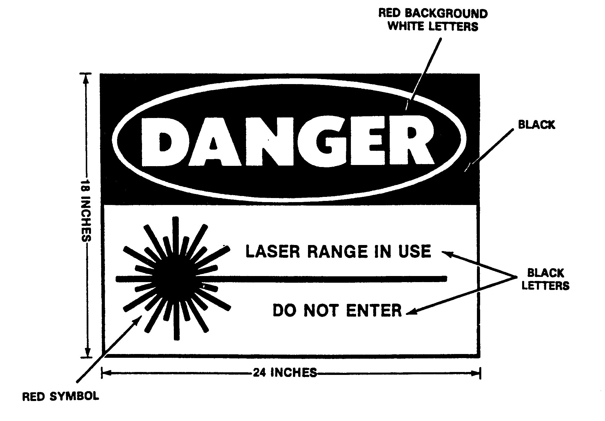
Evaluation of each anticipated operating condition must include development of procedures for ensuring proper placement of warning signs. Local SOPs should provide for the placement of temporary signs during operation. Signs should be in accordance with AR 385-30, SPAWARINST 5100.12B, or AFOSH Std 161-10 (see Figure 4-3).
Form # NAVSEA 1995/17 Stock No. 0118-LF-020-1100
Available from:
Naval Publications and Forms Center
Code 1062
5801 Tabor Avenue
Philadelphia, PA 19120-5099
Order on DD FORM 1348. Provide cost accounting data. Cost $118/package of 5.
Customer Service phone DSN 442-2626.
Figure 4-3. Example: warning sign.
Individuals within the horizontal or vertical LSDZ such as moving target operators, support personnel, and aircrew members should wear laser protective eyewear with curved protective lenses during laser firing. The curved lenses are necessary if there is a probability that laser eye protection will specularly reflect the beam into an uncontrolled area. Eye protection with side shields may be required if the laser beam can get behind the lens. Eyewear must be approved for the wavelength of the laser device being fired. A laser filter designed to protect against one wavelength of laser may not protect against harm from another. Appendix A, Table A-3 provides the wavelength and optical density required for the current fielded devices. If more than one type of device is used, protective measures must cover all devices. For devices of the same wavelength, the highest required optical density will be used.
The use of magnifying daylight optical devices to observe the target during laser operation is permitted if flat mirror like surfaces have been removed from the target area. Mirror like targets can be observed only if appropriate laser safety filters are placed in the optical train of the magnifying optics. Protected optics such as sights must be so marked.
Because NVGs provide a substitute for the human eye during night time operations, NVGs must be considered a mission critical item. Devices such as ANVIS or cats eye, MXU-810/U, are designed for aviators and are as important as the aviator’s eyes during night time operations. Although some NVGs will protect the human eye from laser damage (NOTE: Cats eye NVG will not protect the human eye.) The damage threshold for NVGs may be as low or lower than the damage threshold for the human eye. The impact of damaging the aviator’s NVGs during flight could be fatal. Therefore these devices must be physically (optical or electrical) or procedurally protected from laser damage. Many resources exist to determine the safe operating ranges for NVGs and several service-specific points of contact are listed below:
Naval Research Laboratory
Code 6656
4555 Overlook Avenue
Washington, DC 20375-5345
(202) 767-6978
USA CECOM NVESD, AMSEL-RD-NV-LPD
10221 Burbeck Road, Suite 430
Fort Belvoir, VA 22060-5806
(703) 704-2031
Wright Laboratory/MLPJ Building 651
3005 P Street, Suite 1
Wright Patterson AFB, Ohio 45433-7702
(513) 255-3808, ext-3169
These specific guidelines are provided as a minimum to ensure proper control of hazardous laser energy:
4.11.6 Fire lasers only at authorized targets.
4.11.7 Where possible, use eye-safe attenuating filters over the laser output.
4.11.11 Cease laser operations if the operator or range control is dissatisfied with target tracking.
4.11.12 Cease laser operations if unprotected or unauthorized personnel enter the laser hazard area.
4.11.16 Establish a laser operator training program.
4.11.17.1 maps depicting the targets, target areas, and their laser hazard area;
4.11.17.2 drawings or photographs of the target/targets to be used;
4.11.17.3 run-in headings and flight profiles to be used for airborne laser operations and permissible firing fans for ground based laser operations; and
4.11.17.4 review of mission profiles to prevent misguidance of laser guided weapons (LGW) by ensuring that the LGW or laser spot tracker field of view (FOV) always encompasses the target and does not encompass the space near the laser designator.
USAMRD-BAFB
7914 A Drive
Brooks Air Force Base, Texas 78235-5138
Commercial: (210) 536-4622
DSN: 240-4622
Fax: (210) 536-3450
AL/OEO
8111 18th Street
Brooks Air Force Base, Texas 78238-5215
Commercial: (210) 536-4816
DSN: 240-4816
Fax: (210) 536-3903
AL/AOCO
2507 Kennedy Circle
Brooks Air Force Base, Texas 78235-5117
Commercial: (210) 536-3241
DSN: 240-3241
Fax: (210) 536-5165
Brooks Air Force Base Command Post is manned at all times: DSN 240-3278, Commercial (210) 536-3278
4.11.22 Do not operate the laser or use it experimentally outside the range area without the operation being specifically authorized by the local LSO. Follow the safety procedures of ANSI Z136.1 for laser operations within any indoor firing pretest or laser testing facility. For example, use electrical door interlocks to prevent laser firing if entry door is opened.
4.12 Laser Pre-firing and Post-Firing Restrictions
When lasers are not in use, hazardous laser output shall be prevented by use of such devices as output covers or rotating the laser into the stow position, unless otherwise specifically authorized by the local LSO. The following subparagraphs should be included in pre and post-firing checklists.
Uses of lasers such as the light detection and ranging (LIDARs) or space probes operating continuously in airspace may require additional controls. Besides coordinating these emissions with the FAA and Space Command, automatic shut down features may be necessary to prevent illumination of aircraft above MPE or to prevent glare danger. These shut down features could be a radar beam which senses incoming craft or an aircraft transponder which signals the laser to shut down (see Appendix I).
Laser guided munitions and other laser detectors have unintentionally acquired radiation sources within the field of detection other than the target resulting in fratricide. Fields of detection vary and are specific to individual weapons. All tactics must be planned to ensure that the angle between the laser designator LOS and laser detectors (for example, laser guided munition, laser spot tracker, and NVG) will not mistakenly aim the munition at the laser source or scattered radiation from the laser platform, see Joint Chiefs of Staff publication 3-09.1 (JLASER).
4.14.1 Ground Laser Designators. When employing laser spot trackers with ground laser target designators, the following procedures will be used
4.14.1.1 Terminal controllers will provide aircrews with an attack heading or laser-to-target line. The attack heading must allow aircrews to acquire the laser energy reflected from the target. Ensure designators for other targets on the range are not using the same laser codes.
4.14.1.2 Because of the possibility of false target indications caused by atmospheric scatter from the laser beam within short distances from the laser exit port, attack headings should avoid target-to-laser designator safety cones unless the tactical situation can safely dictate otherwise. (The safety cone is usually defined as a 20o cone whose apex is at the target and extends 10o degrees either side of the target-to-laser designator line.) The scattered radiation that the seeker can detect may be caused by both Rayleigh and Mie scattering. Rayleigh scattering of radiation from atmospheric molecules is what makes the sky blue. It is strongest for shorter wavelengths (varies inversely by the fourth power of the wavelength) and is about twice as strong at 0o and 180o than at 90o from the laser LOS. However, at 90 degrees, it shows the greatest polarization. Mie scattering from aerosols is very strong in the forward direction of the beam even in the cleanest of atmospheres. It is not as dependent on wavelength as Rayleigh scattering and has no strong polarizing effect.
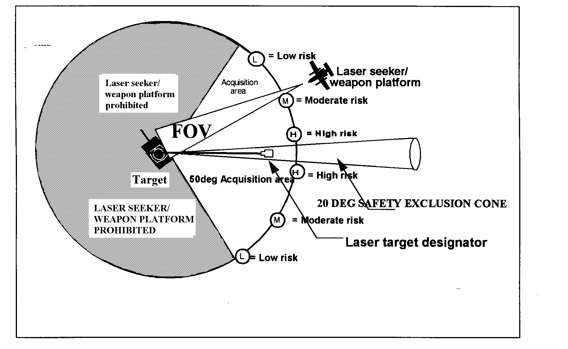
4.14.1.3 The optimal attack zone is a 50o zone from 10o to 60o either side of the target-to-laser designator line and at an elevation that will ensure adequate target acquisition. The risk of acquiring the laser designator instead of the target in this zone varies from moderate to low as the angle increases.
4.14.1.4 WARNING. The degree of hazard to ground personnel operating the laser target designator varies with the attack angle of Laser Spot Tracker from the laser LOS. See Figure 4-4. In some situations, laser spot trackers have shifted from the designated target to the laser target designator while operating in the 50o attack zone. For this reason, laser spot trackers should not be used as the sole source for target verification. Aircrews should verify they are attacking the target through additional means such as visual description or non-laser target mark. At a minimum, the laser spot cue provided in the cockpit must be evaluated and compared to the expected target location. For close air support missions, the target location given in line 6 of the 9-line brief should be used to confirm the laser spot. For aircraft equipped with an Inertial Navigation System (INS) or Global Positioning System (GPS), steering cues provided by these aids should always be used to back-up the laser mark. Additional aids include, but are not limited to, visual target description, laser pointers, or non-laser target marks provided by direct or indirect fire from conventional weapons. If the laser spot tracker cue is not coincident with the expected target location, aircrew should not deliver ordnance on the laser spot.
To reduce the potential for seeker lock-on to the designator position, the designator should be masked from the seeker field of view. Terrain, vegetation, or other obstruction can sometimes mask the designator.
WARNING: DOES NOT GUARANTEE THAT THE LASER
SEEKER WILL NOT LOCK ONTO THE LASER DESIGNATOR.
When the seeker's acquisition can be monitored by watching the aircraft with the laser spot tracker or seeing a laser guided bomb (LGB), it may be possible to detect an improper lock-on in time to prevent a mishap by aborting the bombing run. See Figures 4-4 and 4-5 for an example of a plan for ground laser designator tactics. Refer to individual Laser Spot Tracker/Laser Guided Weapons technical orders and procedures for additional safety information.
NOTE : Situational check must ensure seeker field of view covers the target and not the area of the laser target designator out to a distance in front of the designator where scatter cannot be detected by the seeker. Because this is an example, details should be obtained from system specific documents and publications such as JCS PUB 3-09.1.
4.14.2 Airborne Wingman Laser Designation. Laser guided weapons (LGW) or laser spot trackers (LST) can erroneously lock onto the scattered radiation from buddy lase or wingman aircraft laser designators. In addition, if the airborne laser designator is pointing towards the LGW or LST, the designator itself may be tracked. In lock-on-before-launch (LOBL) mode, the LGW seeker LOS can be displayed in most launch aircraft. If the LOS cue is well above the horizon, then the missile is probably locked onto an erroneous spot such as the designator aircraft or atmospheric scatter instead of the desired target spot, and the mission should be aborted. If the LGW is employed in the lock-on-after-launch (LOAL) mode, no LGW LOS cueing is provided to the launch aircrew. Wingman designators must be aware that even if a LOBL is planned, launch aircrews train to employ the missile in a LOAL mode if a laser spot is not received once clearance to launch has been given.
4.14.2.1 If the missile properly locks onto the target in an LOBL mode, the only risk to the designator would be a midair potential if the designator aircraft is operating below the missile trajectory apex. In an LOBL mode, the wingman aircraft altitude should remain substantially above the nominal LGW apex altitude, keeping in mind that missiles can climb to altitudes well in excess of their nominal apex values especially if they are tracking a laser designator.
4.14.2.2 When employed in an LOAL mode, the laser guided missile will execute a climbing profile searching for a laser coded energy prior to tipping over and scanning its FOV along the ground. The risk to the wingman designator is highest during the initial staring phase of the LGW profile. If it locks onto the designating aircraft, there is a high probability that it will track and kill the laser designator. The dimensions of the instantaneous FOVs of the LGWs are not absolute, and some are capable of detecting forward or back scattered radiation at many degrees off boresight.
4.14.2.3 The geometry and timing for buddy/wingman lase tactics must be precise to preclude the weapon from targeting the designating platform. Designator profiles behind the launch platform are inherently the safest. If that is not possible, a designator profile must be selected that will keep the aircraft out of the LGW FOV. Figures 4-6, 4-7, 4-8 and 4-9 show examples of laser designator NO FLY CONE profiles. Refer to individual LST/LSW technical orders and procedures for additional safety information. Ensure other designators on the range are not using the same laser code.
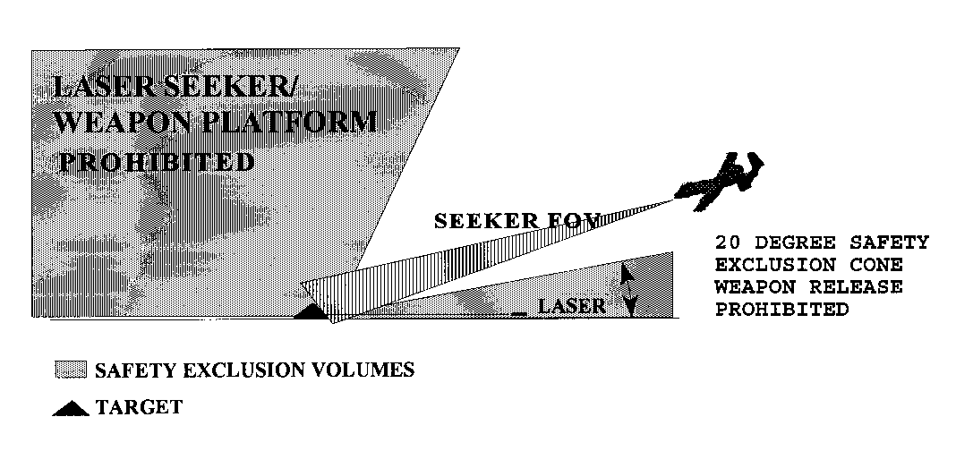
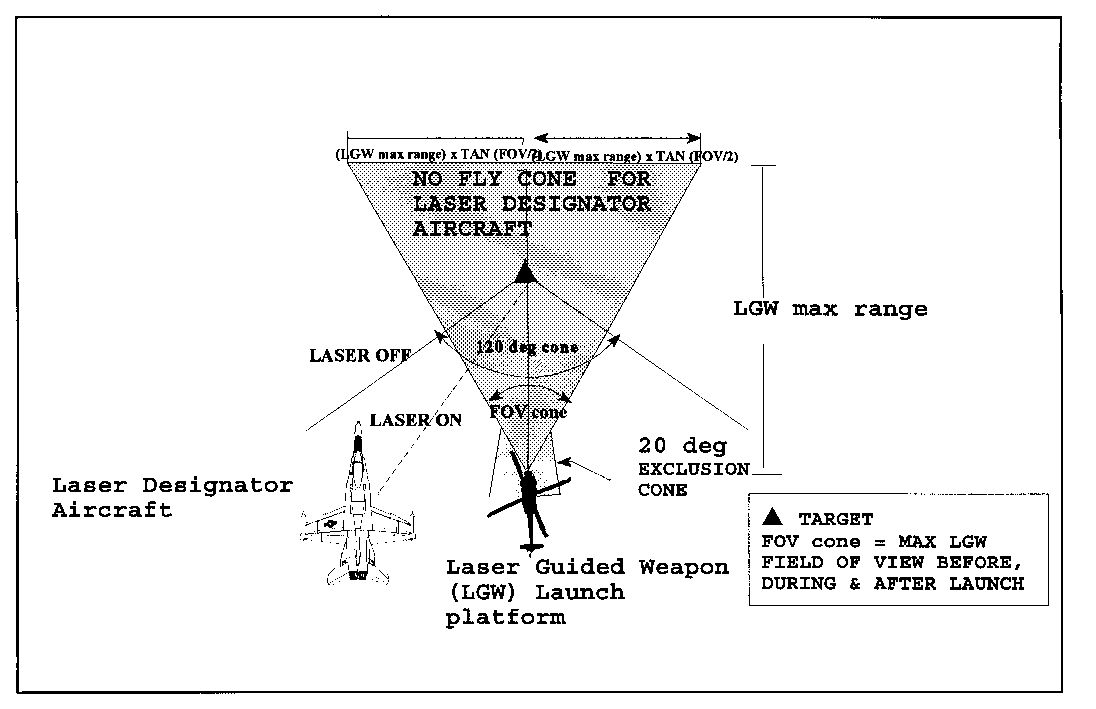
Figure 4-7. Sample vertical view of safety exclusion cones to prevent homing on
continuous laser designator aircraft.
NOTE: To minimize risk of fratricide, ensure the target is always in the seeker FOV when the laser designator is on and minimize intersection of the laser seeker FOV with the laser beam especially close to the laser.
RANGE EVALUATION
PLANNING REQUIREMENTS
Prior to any laser range operations, the hazards of using the system on the range must be fully evaluated. Both the laser user and the range control personnel must mutually agree on the conditions for laser operations. A sample checklist is provided in Appendix F for this data collection.
The laser user shall provide
5.2.3 standard operating procedures on the laser;
5.2.5 laser systems parameters; and
The range operator shall provide
5.3.1 local instructions that outline general range operating and safety requirements and
The range evaluator will review laser system data, maps, targets, instructions, SOPs, and other information provided by the laser user and range operator to determine which existing requirements impact the safety of laser operations on the range such as
5.4.1 limitations on allowable laser locations and run-in headings for aircraft,
5.4.2 minimum and maximum flight altitudes (airborne platforms only),
5.4.4 flyover requirements to ensure range security,
5.4.5 locations of control towers and other manned areas
5.4.6 locations of non-controlled personnel access to the areas surrounding the target area, and
5.4.7 specific information on maintenance, boresighting, or other activities on the range.
RANGE EVALUATION REQUIREMENTS
A laser range evaluation can be performed for a specific laser system or for a group of similar lasers. An evaluation of a group of similar lasers is recommended if available land permits and the mission is not severely impacted. To perform this general evaluation, the worst case conditions of all possible systems and missions are used. If these conditions are too restrictive, separate evaluations for each system must be performed. The evaluation should be conducted on site at the laser range including a flyover, drive-through, and walk-through inspection. To simplify the range evaluation procedure, it may be divided into five steps: laser; range; target; mission; and laser surface danger zone.
6.1.1.1 Maximum Permissible Exposure (MPE) Limits. Determine the applicable MPE for the laser being evaluated. The MPEs are provided in ANSI Z136.1.
6.1.1.2 Laser Classification. Classify the laser using the procedures in MIL-STD-1425 to determine what laser control procedures are required such as interlocks and warning labels.
6.1.1.3 Nominal Ocular Hazard Distance. Determine the distance from an operating laser to the point where the laser is no longer an eye hazard by using the procedures designated by the specialists listed in subparagraph 1.2.2 or use the values given in appendixes A and C.
6.1.1.4 Reflections. Determine if the laser is capable of producing hazardous reflections under established conditions using procedures designated by specialists listed in subparagraph 1.2.2 or appendixes A and C.
6.1.1.4.1 Specular Reflections. Determine what kinds of surfaces will act as specular reflectors at the laser wavelength (see Figure 6-1, Table 6-1, and Appendix G).
6.1.1.4.2 Diffuse Reflections. Determine if the laser is capable of producing hazardous diffuse reflections. Lasers that can produce hazardous diffuse reflections are classified as class 4 and have an associated diffuse reflection hazard distance (t). It is unusual for field type lasers to produce diffuse hazards. Presently, only the M60 tank, the M551A1 Sheridan Vehicle, and the OV-10D Night Observation System produce hazardous diffuse reflections. Normally for a diffuse hazard, the beam path out to the distance,t, as provided in Table A-1, is a denied occupancy area and no objects are permitted in the beam path out to this distance.
TABLE 6-1. Typical Reflective Surfaces
6.1.1.5 Optical Density. The degree of protection required to reduce the incident laser energy to safe eye and skin levels must be determined. These levels are available in appendixes A and B and from the designated specialists listed in subparagraph 1.2.2.
6.1.1.6 Optical Viewing. Consider the possibility of personnel directly viewing the beam (intrabeam viewing) or reflections of the beam through optical instruments such as binoculars. The light gathering ability of the optics can significantly increase the degree of hazard for the eyes (increase OD and NOHD). Procedures to evaluate this hazard are in AFOSH Standard 161-10, ANSI Z136.1, and TB MED 524. Some evaluation results are included in appendixes A and B.
6.1.1.7 Atmospheric Attenuation. Atmospheric attenuation can be quite high for infrared lasers operating over distances of 10 kilometers or greater. It can reduce the NOHD considerably and should, therefore, be included in the laser evaluation.
6.1.1.8 Laser Platform Stability. The stability of the laser platform must be evaluated to determine the pointing accuracy of the laser system. The pointing accuracy will determine the size of the buffer angle. The typical buffer angle for airborne (aircraft), ground based, or shipboard stable platforms (tripods) is 5 milliradians, while hand-held lasers normally require 10 milliradians. Paragraph 6.8.1 further discuss the buffer angle.
6.1.2.1 Range Map. The range map is essential to establish accurate distances from target area to range boundaries. The range map should show the boundaries and include geographic items such as towers and buildings. Boundaries of special purpose areas such as an airstrip and the location of the targets are required.
6.1.2.2 Topographic Map. The topographic map is important because it enables the evaluator to determine the elevation of the target area relative to the surrounding terrain. It is important that no portion of the beam, which exceeds the MPE limits, extends beyond the controlled area. Using natural geographic backstops such as hills can control the beam. A topographic map is very helpful in identifying these backstops and in repositioning targets if necessary.
6.1.2.3 Airspace Map. Controlled airspace is that airspace associated with the range having specific, possibly non-coincident lateral boundaries and a specific minimum and maximum altitude. It is important that this controlled airspace and any other special conditions are made known. Laser operations are not normally authorized outside the controlled airspace or when other aircraft are between the laser and the target. In addition, if the beam is directed up, or if hazardous reflections could exceed the height of the controlled airspace, additional controls may be necessary.
6.1.3.1 Optimum Target. The optimum target from a safety point of view is a non-reflective surface. Flat specular surfaces must be removed or covered, because reflections from these surfaces can retain high collimation. A flat specular surface is one in which a relatively undistorted image can be seen. Examples of specular surfaces are windows, Army tank vision blocks, searchlight cover glass, plastic sheets, glossy painted surfaces, still water, clean ice, flat chrome, and mirrors. Snow is not a specular surface, but if thawed and refrozen, hazardous reflections can be found especially at low angles of incidence. Glossy foliage, raindrops, and other natural objects are not hazardous targets since their curved reflective surfaces as well as other curved reflective surfaces cause the beam to spread and the reflected irradiance (energy per unit area) decreases quickly with distance. The only exception is concave reflective surfaces, which can focus the reflected beam and cause the reflection to be more hazardous than the incident beam. Practically, these reflections are of little concern because it is improbable that the surface is perfectly concave (focuses the beam to a single point) or perfectly reflective. Additionally, the focal points of concave reflectors would probably be very close to the object (small radius of curvature) and be of little concern, because people do not normally put their head close to objects and if they did, they would probably block the incident beam. Concave surfaces with a large radius of curvature which could focus at longer distances would appear nearly flat and must be removed or covered. Although curved surface reflection may not be hazardous at typical laser-to-target engagement ranges, large shiny curved surfaces should be removed. An example of such a surface is a curved automobile bumper. Lastly, a diffuse surface is one that totally distorts (or diffuses) the beam shape, normally resulting in a safe-to-view reflection from outside the target area. Table 6-1 lists some common items found in a typical range area and their type classification for reflection. Appendix G provides additional information.
6.1.3.2 Size and Location. The number and location of targets (distribution) will affect the size of the hazard zone. On ranges with limited space, it is important that all targets be as close together as tactically feasible.
6.1.3.3 Separate Target. See Appendix H for Navy separate target (SEPTAR) operations.
6.1.4.1 Air-to-Ground. Determine desired flight profiles. Flight information necessary to perform an evaluation is altitudes, ranges, and directions of the aircraft relative to the target during laser operations. Various terms are used to describe the aircraft direction during ordnance delivery; they include approach track, attack heading, and run-in heading. These headings can be on a single bearing, a range of bearings, and unrestricted approach (360o). Typical mission profiles are
Toss Delivery, General Profile
Slant Range: 1,800 - 70,000 feet
Altitude: 200 - 2,600 feet
Toss Delivery, Mode A
Slant range: 20,000 - 70,000 feet
Altitude: 200 - 320 feet
Toss Delivery, Mode B
Slant range: 10,000 - 25,000 feet
Altitude: 1,000 - 3,400 feet
Straight and Level Delivery
Slant range: l,800 - 30,000 feet
Altitude: 1,500 -3,300 feet
Dive Delivery
Slant range: 8,500 - 14,000 feet
Altitude: 4,000 - 7,600 feet
6.1.4.2 Ground-to-Ground. Determine possible laser locations and direction of laser operations.
6.1.4.3 Ship-to-Target. Determine the possible laser locations, direction of laser operations, and ship headings.
6.1.5 Laser Surface Danger Zone. The LSDZ (also called the buffered laser footprint for airborne and elevated lasers) must be determined using the procedures provided in Paragraphs 6.3, 6.5, 6.7, 6.8, and 6.9.
6.2 Target and Target Area Condition
Careful attention must be paid to the condition of the target and surrounding laser hazard area. Any specular reflectors on or around the laser targets must be either removed or rendered diffuse. Specular reflectors may be rendered diffuse by painting with a flat (non-specularly reflecting) paint. Merely covering a specular reflector is not adequate, because the covering material is usually susceptible to ordnance damage. The position and orientation of any specular reflectors that cannot be removed or rendered diffuse must be noted, so they can be considered during the laser safety evaluation. Generally, specular reflectors larger than .0.5 inch in diameter must be removed from the LSDZ. If this is too restrictive, individual LSOs may refer to the specialists in subparagraph 1.2.2. Target area conditions should be reviewed periodically as determined necessary by local safety authority.
To meet mission requirements, the stability, pointing accuracy, and boresight retention capabilities of a laser rangefinder and designator system must exceed those required for range safety. Described in the following subparagraphs are buffer zones and laser variety.
The LSDZ consists of the target area plus the horizontal and vertical buffer zones (see Figure 6.2) and considers both direct hazards (main beam) and indirect hazards (reflections). The boundaries of the LSDZ depend on which of the two overlapping zones, direct hazard or the indirect hazard, is larger. If there are no specular reflectors on the range and the laser is not a diffuse reflection hazard, there will not be an indirect hazard zone. The direct hazard zone will always exist if laser-to-target distance is less than the NOHD. The LSDZ includes the laser beam plus a buffer zone around the beam to account for laser platform instability. The three types of LSDZs and the dimensions are described in the following subparagraphs.
Figure 6-2. Laser surface danger zone.
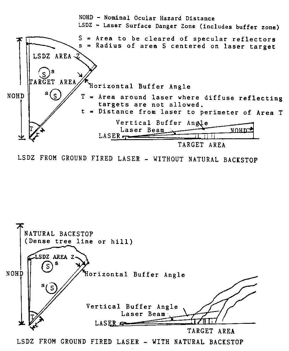
Figure 6-3. LSDZ without and with natural backstop.
6.4.4.1 Existing Surface Danger Zones. Existing munitions surface danger zones for direct fire weapons are usually large enough to provide the required horizontal and vertical buffer zones for ground-to-ground laser operations provided the beam is terminated in the impact area (see Figures 6-5 and 6-6).
6.4.4.2 Distance of the Laser Surface Danger Zone. The following combination of NOHD and terrain features must be considered in controlling laser hazards.
6.4.4.2.1 When viewing the collimated beam with a telescope, the hazardous range is greatly increased. For example, a 10-km NOHD would be increased to 80 km for an individual looking back at the laser from within the beam with 13 power optics. Such large amounts of real estate are difficult to control. The solution is to use a backstop behind the target.
6.4.4.2.2 On the ground, this area normally extends to an adequate backstop or the NOHD. Laser operations at targets on the horizon is permitted as long as air space is controlled to the NOHD. In this case, the LSDZ extends downrange to the NOHD in the airspace and to the skyline on the ground as seen from the laser position (see Figure 6-6). Operators and crews will conduct laser operations only at approved targets. Usually, when there are no natural backstops available (for example, mountains), the magnified NOHD-O (O indicates optics) may extend out to extremely long ranges (for instance, 80 km for tank-mounted laser rangefinder (LRF)). This extreme situation would only create ocular hazards if (1) there was a direct LOS to an observer on the ground, and (2) there is a possibility that the observer could be engaged in direct intrabeam viewing with unfiltered magnifying optics.
6.4.4.2.3 Unless the NOHD or NOHD-O has been exceeded, the hazard distance of the laser device is the distance to the backstop. This hazard distance must be controlled. The terrain profile from the laser device's field of view plays a very important role, because the laser presents only a LOS hazard. The optimal use of natural backstops is the obvious key of minimizing laser range control problems.
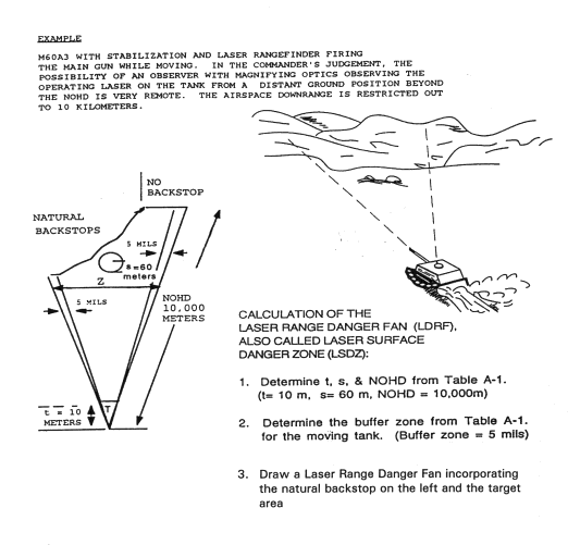
Figure 6.4. Example laser range danger fan/laser surface danger zone.
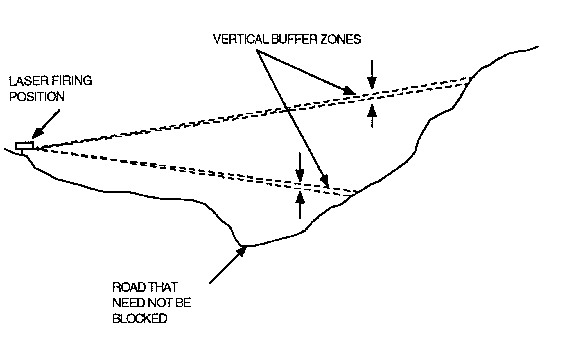
Figure 6-5. Vertical buffer zone.
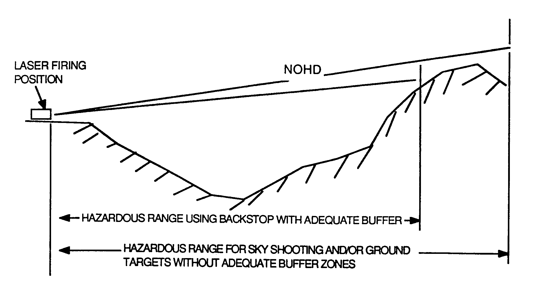
Figure 6.6. Effects of backstops.
6.4.4.3 Buffer Zones. The extent of horizontal and vertical buffer zones around the target area, as viewed from the firing area, depends on the aiming accuracy and stability of the laser device. The laser horizontal buffer zones could partially or completely be included in lateral safety or ricochet areas on ranges where the laser is used with live fire weapons. Table A-1, lists buffer zone values for currently fielded equipment.
6.5 Range Facilities Evaluation
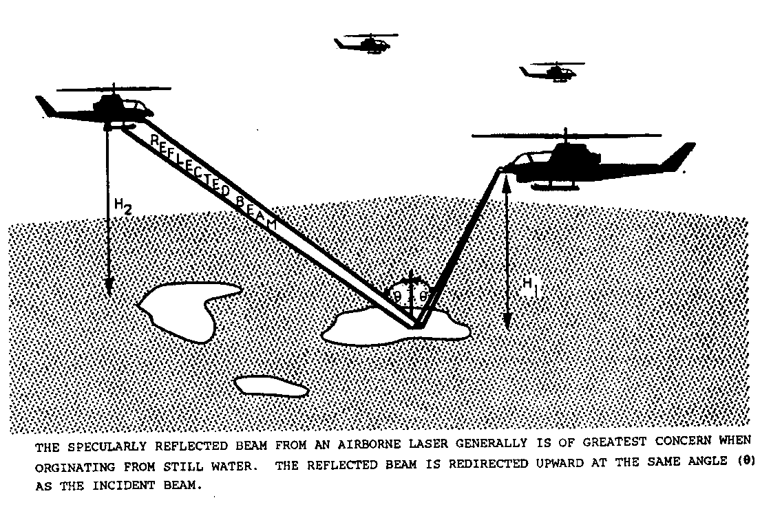
Figure 6-7. Example of airborne beam reflection.
A visual survey of the range area is often very useful. The survey should be conducted from actual firing locations and target locations. If the target is used for aerial operations, the range evaluator should, whenever possible, perform an aerial fly-over on the proposed or approved laser run-in headings. A pair of binoculars with an angular calibrated reticle can be used to scan the terrain features to estimate the natural buffer area. Suitable areas should be marked on a current map. Do not rely entirely upon the contour lines on the range map, because they may result in an erroneous estimation of the buffer area. Actual targets should be visually inspected for specular reflectors before their insertion on the range to ensure that these surfaces are removed. Conversion of an impact area to a laser range area may require overflights to observe any glints of sunlight reflecting from broken bits of glass or other reflectors laying on the ground.
Laser system parameters may vary greatly with laser location, look angle, support structure and laser characteristics. The effects of these parameters are provided in the following subparagraphs.
Calculate the size of the beam which irradiates the ground or ground-based, sea-based, or airborne target (footprint). Normally, laser beams are circular, diverge equally in all directions, and produce cone shaped beams. The size of the beam depends on the initial beam diameter, divergence, and distance (slant range) from the source. The size of the footprint is the size of the beam plus a buffer zone (see Figure 6.8). For scanning systems, the size of the beam would include all positions in the scan. The shape of the footprint depends on the angle of the beam that intersects the ground. (Slant angle is determined from the range and altitude.) The footprint is determined by buffer angle and size which are described in the following subparagraphs.
6.8.1.1 If the aiming accuracy for a stabilized laser is unknown, buffered footprint angular width will be 5 milliradians either side of the beam.
6.8.1.2 If the aiming accuracy is known, the buffered footprint angular width will be 5 milliradians, or the absolute value of the aiming uncertainty (in milliradians) plus 5 times the beam divergence at the 1/e (.3679) point, whichever is less, either side of the laser beam. Aiming accuracy should be contained in the system specifications.
6.9.1 Moving Targets or Lasers. A moving target or laser will affect the size of the LSDZ and may indicate that the single pulse NOHD is more applicable than the multiple pulse NOHD, especially when evaluating specular reflections. This range layout must be decided on a case-by-case basis. A common application includes evaluating reflection hazards when the angle of laser operations is rapidly changing, and therefore, the probability of a multiple pulse exposure is small.
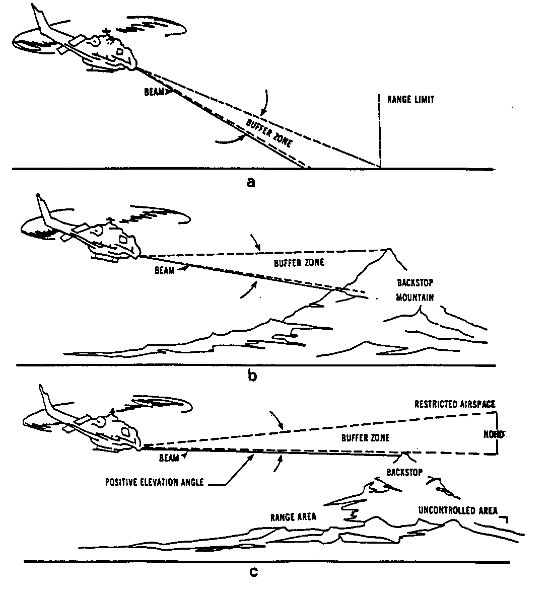
Figure 6-8. Examples of the use of natural backstops, buffer zones, and restricted air space.
6.9.2 Operating Outside of Controlled Area. Targets should never be positioned outside the controlled area (including airspace). Airborne lasers should not be operated outside the controlled airspace if the potential for the beam striking an object outside the controlled area exists. If this risk is minimal, consider permitting laser operations from uncontrolled areas under controlled conditions. Ensure the regional Flight Service Center for the Federal Aviation Administration (FAA) and Coast Guard is notified before starting this operation, so they can publish a Notice to Airmen and Mariners. The FAA regulation governing this is 7930.2B, Notices to Airmen (NOTAM). Ground laser systems should never be operated outside the controlled area.
6.10 Range Control Procedures and Recommendations
Laser range safety shall prevent exposure of unprotected personnel from laser radiation in excess of the MPE. This objective can be met by determining where the laser radiation is expected to be, restricting access of unprotected personnel, and removing reflective surfaces from this area.
6.10.6 Eye Wear. Personnel within the LSDZ shall wear laser protective eye wear during laser operations. Eye wear must be approved for the wavelength of the laser system being used and must provide sufficient protection (see Appendix A, Tables A-3 and A-4). If more than one type of laser is used, protective eye wear must provide adequate protection for all wavelengths involved (OD greater or equal to the largest minimum OD required for each wavelength).
Figure 6-9. Supervised laser demonstration for military training.
(Modified from ANSI Z136.1, Figure 2D)
USER LEVEL LASER INSTRUCTIONS
Using the laser range safety evaluation, the range planner/LSO will determine the necessary information to
7.1.1 prepare or modify range laser safety directives,
7.1.2 develop SOP for laser operations,
7.1.4 prescribe the personal protective equipment to be used.
The laser range safety evaluation should be used to review and to ensure overall range safety regulations are current. Regulations should be developed or updated as necessary to take into account new laser systems, operating areas, and targets.
7.3 Standard Operating Procedures
The SOPs for specific laser devices should inform laser users of the potential hazards from the laser devices under their control during laser operation. Checklists for evaluating SOP are provided in Appendix F. An SOP should be prepared concerning procedures for a presweep of the range before a laser operation to ensure unprotected personnel are not in the target area and to maintain radio communications.
In addition to instructions on particular devices or simulators, training material required for classroom instructors and range personnel should include.
7.4.1 principles of reflection or refraction of light,
7.4.2 hazards of laser beams to humans and misconceptions about laser effects,
7.4.3 safety standards or operational control procedures, and
Eye protection requirements are listed in Appendix A, Table A-3.
Laser indoctrination should be provided at the same time as the basic weapons systems instruction to students taking advanced individual training and to officers taking basic courses. The classroom instructors must be knowledgeable in operator and crew aspects of laser safety. Reference publications on subject lasers should be readily available. The instruction presented should be at the user level. (Complex scientific data or terminology should be avoided.) A training film, if available, should be included in the instruction program. Hazard data for lasers as incorporated into the technical manual on the related weapon system or on the laser component should be stressed. Proper channels for obtaining professional safety and medical assistance should be addressed during indoctrination.
APPENDIX A
LASER SAFETY INFORMATION
FOR FIRE CONTROL LASER SYSTEMS
APPENDIX A
LASER SAFETY INFORMATION
FOR FIRE CONTROL LASER SYSTEMS
This appendix provides safety information for currently fielded laser fire control systems.
2.0 Fire Control Laser Safety Features
Fire control laser systems are laser rangefinders (LRFs) and laser designators (LDs). These laser systems can be far more harmful to the eye than laser training devices such as MILES and Air-to-Ground Engagement System/Air Defense (AGES/AD) laser simulators. Consequently, fire control lasers require control measures to prevent permanent blindness to an unprotected individual viewing the laser system from within the laser beam. A sample list of control measures for operators of fire control lasers is provided in Appendix H.
|
TABLE A-1. NOHD (ATMOSPHERIC ATTENUATED) AND RANGE SAFETY INFORMATION FOR FIELDED MILITARY LASER SYSTEMS |
|
REFLECTOR BUFFER ZONES Device/Mounting NOHD NOHD-O CLEARANCE (Buffer Angle) _____ _ ___ ___ t1 _____ s2 __ (Each Side) Multi- Single 7X50 8 cm 12 cm Diffuse Static Moving Pulse Pulse Binoc. Optics Optics Specular (Kilometers) (Kilometers) (Meters) (Milliradians) |
|
TANK MOUNTED AN/VVG-1(M551A1) 9 9 32 47 67 10 60 2 Not allowedAN/VVS-1(M60A2) 9 9 32 36 44 10 100 5 10 AN/VVG-2(M60A3) 8 8 30 40 47 10 60 2 5 red ESSLR(29dB) 0.3 0.3 1.8 0 Target 2 5 green ESSLR(55dB) 0 0 0 0 0 0 0 NA NA AN/VVG-3(M1Tank) 7 7 25 35 44 0 60 2 5 ESSLR 0 0 0 0 0 0 0 NA NA AVENGER 0 0 0 0 0 LAV-105 8.2 32 41 50 0 60 2 5 LAV-AD 0 0 0 0 0
MAN PORTABLE AN/GAQ-T1(LD82LB LDSS) 12.5 - - 43 52 0 200 5 NA AN/GVS-5(Handheld) 2.7 2.7 13 21 27 0 200 10 NA 19dB red filter 0.29 0.29 1.8 1.8 - 0 200 10 NA 29dB yell. Filt 0.056 0.056 0.55 0.55 - 0 200 10 NA |
1
t = distance from the laser in the laser beam path in which there is both a skin hazardand diffuse reflection hazard. Represents the range to be cleared in front of the tank.
2 s = distance around the target out to which specular reflectors must be cleared
when laser is level or nearly level with target.
|
TABLE A-1. NOHD (ATMOSPHERIC ATTENUATED) AND RANGE SAFETY INFORMATION FOR FIELDED MILITARY LASER SYSTEMS (continued) |
|
REFLECTOR BUFFER ZONES Device/Mounting NOHD NOHD-O CLEARANCE (Buffer Angle) _____ _ ___ ___ t1 _____ s2 __ (Each Side) Multi- Single 7X50 8 cm 12 cm Diffuse Static Moving Pulse Pulse Binoc. Optics Optics Specular (Kilometers) (Kilometers) (Meters) (Milliradians) |
|
MAN PORTABLE AN/PAQ-1 (Handheld LTD) 7 3.5 15 33 - 0 200 10 NA AN/PAQ-3 MULE (Tripod) Designator-Day 20 12 53 64 78 0 60 2 NA Designator-Night 20 12 53 64 78 0 150 5 NA RangeFinder-Day 12 12 37 47 - 0 60 2 NA Rangefinder-Night 12 12 37 47 - 0 150 5 NA Rangefinder with 12dB filter 3.3 3.3 16 - - 0 60 2 NA AN/PAQ-3 MULE (Handheld) Designator-Day 20 12 53 64 78 0 200 10 NA Designator-Night 20 12 53 64 78 0 300 15 NA Rangefinder-Day 12 12 37 47 - 0 200 10 NA Rangefinder-Night 12 12 37 47 - 0 300 15 NA AN/PAQ-4/A/B/C IR Aiming Light 0 0 0 0 0 0 0 0 A AN/PEQ-1 (SOFLAM) 9.6 - 35 45 54 0 200 10 NA
|
1
t = distance from the laser in the laser beam path in which there is both a skin hazard and diffuse reflectionhazard. Range to be cleared in front of the laser.
2 s = distance around the target out to which specular reflectors must be cleared
when laser is level or nearly level with target.
|
TABLE A-1. NOHD (Atmospheric Attenuated) and Range Safety Information for Fielded Military Laser Systems (continued) |
|
REFLECTOR BUFFER ZONES Device/Mounting NOHD NOHD-O CLEARANCE (Buffer Angle) _____ _ ___ ___ t1 _____ s2 __ (Each Side) Multi- Single 7X50 8 cm 12 cm Diffuse Static Moving Pulse Pulse Binoc. Optics Optics Specular (Kilometers) (Kilometers) (Meters) (Milliradians) |
|
MAN PORTABLE AN/PEQ-2 (ITPIAL) Aim light and Illuminator 0.263 - 1.8 2.8 4.7 0 20 10 NA Iluminator only 0.211 - 1.5 2.3 3.9 0 20 10 NA Aim Light (High) 0.078 - 0.56 0.88 1.5 0 20 10 NA Aim Light (Low) 0 0 0 0 0 0 0 NA AN/PVS-6 (MELIOS) 0 0 0 0 0 0 0 0 AN/PVS-X MLRF Mini-Laser Rangefinder - 3 16 29 - 0 200 90o3
AN/TVQ-2 GVLLD (Tripod) Designator 25 17 63 80 87 0 60 2 NA Rangefinder 8 8 28.5 40 - 0 60 2 NA Rangefinder with 8.5dB yell.filter 3.1 3.1 15 23 - 0 100 2 NA CLD(Compact Laser Designator) 9.7 - 38 48 58 0 200 10 NA LLTD 7 - 15 38 - 0 200 10 NA
|
1
t = distance from the laser in the laser beam path in which there is both a skinhazard and diffuse reflection hazard. Range to be cleared in front of the laser.
2
s = distance around the target out to which specular reflectors must be clearedwhen laser is level or nearly level with target.
3
90o buffer zone required for RCA version AN/PVS-X with secondary beams.10o buffer zone required for Brunswick version.
|
TABLE A-1. NOHD (ATMOSPHERIC ATTENUATED) AND RANGE SAFETY INFORMATION FOR FIELDED MILITARY LASER SYSTEMS (continued) |
|
REFLECTOR BUFFER ZONES Device/Mounting NOHD NOHD-O CLEARANCE (Buffer Angle) _____ _ ___ ___ t1 _____ s2 __ (Each Side) Multi- Single 7X50 8 cm 12 cm Diffuse Static Moving Pulse Pulse Binoc. Optics Optics Specular (Kilometers) (Kilometers) (Meters) (Milliradians) |
|
AIRCRAFT MOUNTED LASERS AH-1W Night Targeting System (NTS) 15 9.2 48 59 69 0 100 5 5
AN/AAS-33A(A-6E TRAM) 14.6 9 - 58 67 0 N/A N/A 5 AN/AAS-37(OV-10D NOS) 11.2 7.1 45 56 59 35 N/A N/A 5 AN/AAS-38A 17 10 50 63 73 0 N/A N/A 5 (F/A-18) AN/ASQ-153(F-4E PAVE SPIKE) 10 6.8 - 48 58 0 N/A N/A 5 AN/AVQ-25(F-111F PAVE TACK) 16 8.8 - 52 70 0 N/A N/A 5 F-117 18.5 9.5 130 - - 0 N/A N/A TBD (unattenuated) LAAT (AH1F) 5 3.4 15 30 36 0 100 5 5 LANTIRN (Combat mode) 15 11.6 48 59 68 0 N/A N/A 53 (Training mode) 0 0 0 - - 0 0 N/A N/A (Secondary Beam) Maintain 1000 ft separation from other aircraft.
|
1 t = distance from the laser in the laser beam path in which there is both a skin hazard and diffuse reflection hazard. Range to be
cleared in front of the laser.
2 s = distance around the target out to which specular reflectors must be cleared
when laser is level or nearly level with target.
3
Air Force assigned buffer zone is 2 milliradians for LANTIRN. It is general policy for this document that aircraft be assigned aminimum buffer zone of 5 milliradians.
|
TABLE A-1. NOHD (ATMOSPHERIC ATTENUATED) AND RANGE SAFETY INFORMATION FOR FIELDED MILITARY LASER SYSTEMS (continued) |
|
REFLECTOR BUFFER ZONES Device/Mounting NOHD NOHD-O CLEARANCE (Buffer Angle) _____ _ ___ ___ t1 _____ s2 __ (Each Side) Multi- Single 7X50 8 cm 12 cm Diffuse Static Moving Pulse Pulse Binoc. Optics Optics Specular (Kilometers) (Kilometers) (Meters) (Milliradians) |
|
AIRCRAFT MOUNTED LASERS
MMS (OH-58D) 35 23 56 - - 0 100 5 5 NITE EAGLE (UH-1N) 15 11 45 55 65 0 100 5 5 PAVE SPECTRE 8.9 5 63 - - 0 N/A N/A TADS (Apache) 26 16 45 68 - 0 100 5 5 UH-1N Navigational - 720 4.0 6.1 8.6 0 100 5 5 Thermal Imaging System (AN/AAQ-22) AC-130U LIA LTD/R (atten.=0) (atm atten.) TADS (Apache) 26 16 45 68 - 0 100 5 5 SHIP MOUNTED LASERS NMMS 0 0 0 0 0 0 0 0
|
1
t = distance from the laser in the laser beam path in which there is both a skin hazard and diffuse reflection hazard. Range to becleared in front of the laser.
2
s = distance around the target out to which specular reflectors must be cleared
|
TABLE A-2. NOHD (ATMOSPHERIC ATTENUATED) AND RANGE SAFETY INFORMATION FOR COMMERCIAL OFF-THE-SHELF (COTS) MILITARY LASERS* |
|
REFLECTOR BUFFER ZONES Device/Mounting NOHD NOHD-O CLEARANCE (Buffer Angle) _____ _ ___ ___ t1 _____ s2 __ (Each Side) Multi- Single 7X50 8 cm 12 cm Diffuse Static Moving Pulse Pulse Binoc. Optics Optics Specular (Kilometers) (Kilometers) (Meters) (Milliradians) |
|
MAN PORTABLE AIM-1/D 0.075 - 0.460 --- --- 0 20 10 10 AIM-1/DLR 0.150 - 0.860 --- --- 0 20 10 10 LPL-30 0.090 - 0.68 1.1 1.6 0 20 10 10 M-931 0.011 - 0.16 0.28 0.4 0 0 10 10 GCP-1 0.090 0.68 1.1 1.6 0 0 35 35 GCP-1A NITE EYE 0.090 0.68 1.1 1.6 0 0 10 10 HAVIS M16 Aiming Light 0.012 - 0.1 0.17 0.25 0 0 10 10
TD-100/TD-100A 0.1 - - - - 0 30 10 10
AIRCRAFT MOUNTED LASERS
AIM-1/MLR 0.085 - 0.68 1.1 1.6 0 20 10 10 AIM-1/EXL 0.130 - 0.68 1.1 1.6 0 20 10 10 |
1
t = distance from the laser in the laser beam path in which there is both a skin hazard and diffuse reflection hazard. Range to becleared in front of the laser.
2
s = distance around the target out to which specular reflectors must be clearedwhen laser is level or nearly level with target.
THIS HAZARD DATA COULD CHANGE, BECAUSE THE GOVERNMENT HAS NO CONTROL OVER THE MANUFACTURING OF THESE PRODUCTS. THE HAZARD CHARACTERISTICS IN THIS TABLE ARE VALID AS OF THE DATE OF THE GOVERNMENT EVALUATION. PERIODICALLY CHECK WITH THE MANUFACTURER TO ENSURE THE CHARACTERISITCS HAVE NOT CHANGED SINCE THE DATE OF THE LAST GOVERNMENT EVALUATION.
|
TABLE A-3. EYE PROTECTION REQUIREMENTS FOR FIELDED LASERS |
|
Device/Mounting Wavelength Built-in Required Eye Protection (Nanometers) Safety Filter (Optical Density (OD)) (OD)* Unaided Aided Other Aircraft |
|
TANK MOUNTED AN/VVG-1(M551a1) 694.3 clip-on 5 5.8 5.8 AN/VVS-1(M60A2) 694.3 clip-on 5 5.8 5.8 AN/VVG-2(M60A3) 694.3 clip-on 5 5.8 5.8 AN/VVG-3(M1) 1064 5 4.7 4.7 AVENGER 10590 0 0 LAV-AD 10600 0 0 LAV-105 1064 4.0 4.7 MAN PORTABLE AN/GAQ-T1(LD82LB) 1064 YES 4.6 5.5 AN/GVS-5 1064 5 3.7 4.4 AN/PAQ-1(LTD) 1064 4 4.2 5.8 AN/PAQ-3(MULE) 1064 5 3.9 5.6 AN/PAQ-4/A/B/C 830 0 0 AN/PEQ-1 (SOFLAM) 1064 5 4.0 5.3 AN/PVS-6 1540 0 0 AN/TVQ-2(GVLLD) 1064 YES 3.8 5.5 CLD(Compact Laser Designator) 1064 5 4.5 5.4 LLTD 1064 4.0 4.9 MLRF(Mini-Laser Rangefinder) 1064 YES 3.7 3.7 |
|
* Assume that built-in safety filter only protects against the wavelength of the laser in which it is installed and that it does not always protect against other laser wavelengths. |
|
TABLE A-3. EYE PROTECTION REQUIREMENTS FOR FIELDED LASERS (continued) |
|
Device/Mounting Wavelength Built-in Required Eye Protection (Nanometers) Safety Filter (Optical Density (OD)) (OD)* Unaided Aided Other Aircraft |
|
AIRCRAFT MOUNTED AC-130U LIA 807 2.7 LTD/RF 1064 3.0 AH-1W Night Targeting System (NTS) 1064 YES 3.5 5.2 AN/AAQ-22 Navigational Thermal Imaging System 1064 N/A 4.0 4.0 AN/AAS-33A(A-6E TRAM) 1064 4.6 5.8 3.0 AN/AAS-37 (OV-10D NOS) 1064 5.2 5.6 3.0 AN/AAS-38A (F/A-18) 1064 4.3 5.4 3.0 AN/ASQ-153 (F-4E PAVE SPIKE) 1064 4.2 5.6 AN/AVQ-25 (F-111F PAVE TACK) 1064 4.3 5.8 F-117 1064 N/A 4.5 6 LAAT(AH-1F) 1064 YES 3.5 4.8 LANTIRN (Combat Mode) 1064 N/A 4.5 5.6 (Training Mode) 1540 N/A 0 0 MMS(OH-58D) 1064 4.1 5.3 NITE EAGLE (UH-1N) 1064 4.1 5.2 3.7 PAVE SPECTRE 1064 N/A 3.7 5.4 TADS/PNVS(APACHE AAH) 1064 YES 4.0 5.5 |
|
* Assume that built-in safety filter only protects against the wavelength of the laser in which it is installed and that it does not always protect against other laser wavelengths. |
|
TABLE A-4. EYE PROTECTION REQUIREMENTS FOR COTS MILITARY LASERS* |
|
Device/Mounting Wavelength Built-in Required Eye Protection (Nanometers) Safety Filter (Optical Density (OD)) (OD)** Unaided Aided Other Aircraft |
|
MAN PORTABLE GCP-1&1A/ACP-2 800-850 1.7 3.6 HAVIS M16 Aiming Light 850 1.1 1.1 LPL-30 800-850 1.7 1.7 M-931 850 0.7 0.8 NITE EYE 980 1.7 1.7 TD-100 850 1.1 1.1 632.8 0.3 0.3 TD-100A 850 1.1 1.1 670 0.6 0.6 AIRCRAFT MOUNTED
AIM-1/(MLR/EXL/D/DLR) 800-850 1.7 1.7 |
|
* THIS HAZARD DATA COULD CHANGE SINCE THE GOVERNMENT HAS NO CONTROL OVER MANUFACTURING OF THESE PRODUCTS. HAZARD CHARACTERISTICS IN THIS TABLE ARE VALID AS OF THE DATE OF THE GOVERNMENT EVALUATION. PERIODICALLY CHECK WITH THE MANUFACTURER TO ENSURE THAT THE CHARACTERISTICS HAVE NOT CHANGED SINCE THE DATE OF THE LAST GOVERNMENT EVALUATION. ** Assume that built-in safety filter only protects against the wavelength of the laser in which it is installed and that it does not always protect against other laser wavelengths. |
2.5 Eye Protection. Tables A-3 and A-4 summarize the eye protection optical density requirements for worse-case exposure at the laser output (unaided) or when collected with an optical instrument (total). The stated optical densities must be at the laser wavelength, otherwise the stated optical densities may offer very little protection. At longer distances away from the laser, the beam begins to spread out and become less harmful, so less optical density would be required at further distances away from the laser.
2.6 Fielded Laser System Descriptions
AC-130U Laser Illuminator Assembly (LIA) is a near IR illuminator mounted on the AC-130U aircraft (see Air Force Specialists of Paragraph 1.2).
AC-130U Laser Target Designator/Rangefinder LTD/RF is mounted on the AC-130U aircraft.
AH-1W Night Targeting System (NTS): This modification is to the Marine Corps AH-1 Telescopic Sight Unit including night targeting capability through the direct view optics using a Forward Looking Infrared (FLIR) and Laser Target Designator/Rangefinder system with camera and video tracker.
AIM-1: A Class 3b infrared diode aiming laser (830 - 850 nm wavelength) for use with night vision goggles. The AIM/MLR is mounted on Marine Corps XM-218, 50 caliber, M-60 and GAU-17B machine gun mounts. The AIM/EXL version is hard mounted on the AH-1 turret. AIM-1/D, AIM-1/DLR, AIM-1/MLR, AIM-1/EXL devices are integrated into the army AH-1F helicopter or used separately or mounted on army rifles. The ANVIS night vision goggles provide adequate protection against these lasers. CAT'S EYES do not protect against laser radiation.
Air to Ground Engagement System/Air Defense (AGES/AD) is an extension of MILES to air defense simulation.
AN/AAQ-14: LANTIRN System, Low Altitude Navigation and Targeting Infrared System for Night. A two pod system containing a terrain following radar (TFR), forward looking infrared (FLIR), laser designation, and later, a target recognition system. This system is designed to be flown on the F-15E and F-16 and the targeting pod is being integrated into the F-14.
AN/AAQ-22 Navigational Thermal Imaging System (NTIS): Turret mounted FLIR/Laser Rangefinder on the UH-1N helicopter.
AN/AAS-33A, Target Recognition Attack Multisensor (TRAM) laser system. This system is mounted on the A6-E aircraft and has a laser target designator and forward looking infrared (FLIR).
AN/AAS-37, Laser Rangefinder Designator mounted on the Marine Corps OV-10 observation aircraft.
AN/AAS-38A NITE HAWK. Pod mounted on lower left side of F/A-18 aircraft contains a Forward Looking Infrared (FLIR) and laser target designator/rangefinder (LTDR)
AN/GAQ-T1 LDSS: Laser Designator Simulator System.
AN/GVS-5 Laser Rangefinder Infrared Observation Set (handheld).
AN/PAQ-1 (LTD) Laser Target Designator. This is a lightweight, handheld, battery operated laser device. Forward observers use the LTD to designate targets.
AN/PAQ-3 Modular Universal Laser Equipment (MULE). This is a Marine Corps laser designator used with laser energy homing munitions. The MULE is man portable and is used only in a dismounted mode.
AN/PAQ-4, AN/PAQ-4A, pulsed AN/PAQ-4B and AN/PAQ-4C Infrared Aiming Light. These are class 1 military exempt laser systems using an 830 nm wavelength laser diode.
AN/PEQ-1 SOFLAM: Special Operating Forces Laser Marker.
AN/PVS-6 MELIOS. MELIOS was developed for infantry forward observers to measure distance. MELIOS is a class 3a restricted eye safe laser.
AN/TVQ-2 Ground/Vehicle Laser Locator Designator (G/VLLD). The G/VLLD is a principal ranging and laser designating device used by Army artillery forward observers with laser energy homing munitions. The G/VLLD is capable of designating stationary or moving vehicular targets and may be used in a stationary, vehicle mounted, or tripod supported dismounted mode. The primary vehicle mount is the Fire Support Team Vehicle (FISTV).
AN/VVG-1 Laser Rangefinder mounted on the M55lAl Sheridan vehicles.
AN/VVG-2 Laser Rangefinder mounted on the M60A3 tank. Used with two filters, the green Eye Safe Simulated Laser Rangefinder (ESSLR) filter and the red ESSLR filter. The green ESSLR is eye safe, the red ESSLR is less hazardous than the system without filters (see Appendix C).
AN/VVG-3 M1 tank laser rangefinder used with one eye-safe filter.
AN/VVS-1 Laser Rangefinder mounted on the M60A2 tank.
AVENGER: Avenger air defense system, turret mounted laser rangefinder on a HMMWV.
COMPACT LASER DESIGNATOR (CLD): A small, lightweight laser designator and/or rangefinder used by the Navy for target designation.
GCP-1 and ACP-2: Ground and Air Commanders Pointers. Small, lightweight Infrared aiming laser for use with night vision devices in target identification and night illumination. The GCP-1 operates at a power of 30 mw with zoomable beam from 30 o to 0.03 o (approximately 500 to 0.5 milliradians). Built-in sensor prevents operation in daylight; however, it does not sufficiently reduce power in dark conditions to prevent hazardous illumination of unprotected personnel within the NOHD. The GCP-1A and ACP-2 operate at 50 mw and do not incorporate the sensor. The finger mounted ACP-2 is not authorized for use by the Navy and Marine Corps.
Laser Augmented Airborne TOW (LAAT) mounted in the AH-1F COBRA Helicopter. The LAAT system consists of a laser rangefinder and receiver that is incorporated into the M65 tube launched, optically tracked, wire guided (TOW) telescopic sight unit.
LAV-105: Light Armored Vehicle-105 mm gun laser rangefinder.
LAV-AD: Light Armored Vehicle - Air Defense turret mounted CO2 laser rangefinder.
LPL-30: A class 3b infrared diode aiming laser used by command to mark targets of choice to attacking forces equipped with the night vision goggles (NVG). The ANVIS NVGs provide adequate protection against class 3b lasers.
M55, Laser Tank Gunnery Trainer.
Mast Mounted Sight on the OH-58D that, in addition to thermal and optical sensors and imaging instrumentation, incorporates a laser rangefinder and/or designator.
MINI LASER RANGEFINDER (MLRF): A lightweight, handheld Neodymium YAG laser rangefinder. The RCA MLRF listed in Table A-1 is given the designation of AN/PVS-X to distinguish it from future MLRFs, which should not have off-axis radiation that would cause it to have such large buffer zone requirements as the AN/PVS-X.
MILES: Multiple Integrated Laser Engagement System . The MILES system uses low risk lasers and does not require service members to wear protective eyewear during the conduct of training with the MILES system.
NMMS: Navy Mast Mounted Sight. The Navy Mast Mounted Sight is mounted above deck for television and IR imaging and incorporates an eye-safe Class 1 LRF used to give range data for high priority targets such as mines, ships, and small water craft.
NITE EAGLE: FLIR/Laser Designator/Rangefinder turret adapted from the Aquilla system for the U.S. Marine Corps UH-1N helicopters. In training and field testing, prohibit laser firing when the laser in flight is less than 1000 meters from the target. This requirement is needed to prevent loss of track and possibility of the beam wandering off the target during slew and reorientation of the laser as the system passes over the target.
NITE EYE: Illuminator for IR camera. Produced by Air Force Phillips Laboratory. Approved only for use with output power below 30 mw.
PAVE PENNY (AN/AAS-35): Laser tracker pod used on the A-10 and A-7 aircraft. Does not contain a laser.
PAVE SPECTRE (AN/AVQ-19): Laser tracking and designator used on C-130 gunships.
PAVE SPIKE (AN/AVQ-12): Laser tracking and designator pod fitted on F-4 and F-111 aircraft.
PAVE TACK (AN/AVQ-26): Advanced optronics pod containing stabilized turret with FLIR, laser designator and tracker used on the F-4, RF-4, and F-111F aircraft.
SCOFT: SHILLELAGH Conduct of Fire Trainer.
TADS/PNVS: Target Acquisition and Designation System with Pilot Night Vision Sight mounted in the Apache Advanced Attack Helicopter.
TD-100: A day/night aiming laser. For daytime use this device uses a class 2 helium neon visible laser and for nighttime the TD-100 uses a class 3b infrared laser diode. Night vision goggles will provide adequate nighttime protection for personnel viewing the infrared laser.
PAVE ARROW (AN/AVQ-14): This was a laser tracker pod developed for use in conjunction with the PAVE SPOT laser designator used on O-2A FAC spotter planes, C-123, and was planned for use on the F-100. It was eventually merged with the PAVE SWORD program.
PAVE BLIND BAT: The PAVE BLIND BAT consisted of a laser target designator to illuminate targets for the PAVE WAY guided bombs. The PAVE BLIND BAT had an effective range of 18,000 feet and was developed for use by AC-130 gunships to aid supporting fighter aircraft.
PAVE FIRE: Development of laser scanner to aid F-4 Phantoms in securing proper target bearing.
PAVE GAT: Development of a laser rangefinder for use on the B-52G.
PAVE KNIFE (AN/ALQ-10): The original laser designator pod developed by Aeronutronic-Ford and used in combat in Vietnam.
PAVE LANCE: Developmental effort to replace the PAVE KNIFE by improving night capability with the addition of a FLIR in place of the low light television (LLTV). Superseded by PAVE TACK.
PAVE LIGHT (AN/AVQ-9): Stabilized laser designator developed for the F-4 Phantom.
PAVE MACK: Development of laser seeker head for air to ground rockets. Project was also called LARS (Laser Aided Rocket System) and rockets were to be used in conjunction with Forward Air Controller (FAC) mounted PAVE SPOT designator.
PAVE NAIL (AN/AVQ-13): Modification of 18 OV-10 FAC aircraft with stabilized periscopic night sight and laser designator. Program coordinated with PAVE PHANTOM and PAVE SPOT.
PAVE PHANTOM: Addition of an ARN-92 Loran and computer to the F-4D allowing aircraft to store targeting information for eight separate positions illuminated by OV-10 PAVE NAIL.
PAVE POINTED: Palletized gun direction system consisting of a laser designator and/or rangefinder and LLTV employed on a C-123 and forerunner of subsequent gunship fire control stems.
PAVE PRISM: Aerodyne Research effort to develop IR and active laser seekers for use on the ASRAAM air-to-air missile.
PAVE PRONTO: Modification of AC-130 gunships for night attack including an LLTV Electro systems night observation camera, AAD-4, or AAD-6 FLIR and AVQ-17 illuminator.
PAVE SCOPE: Target acquisition aids for jet fighter aircraft such as the Eagle Eye (LAD) AN/AVG-8, and TISEO.
PAVE SHIELD: Classified project undertaken by Aeronautical Research Associates.
PAVE SPOT (AN/AVQ-12): Stabilized periscopic night vision sight developed by Varo for use on the O-2A FAC. The system was fitted with a Korad laser designator (ND:YAG).
PAVE STRIKE: A related group of air-to-ground strike programs include PAVE TACK and IR guided bombs.
PAVE SWORD (AN/AVQ-11): Laser tracker designed to pick up energy from targets illuminated by O-2A spotter planes. Used on F-4, and bore sighted with its radar set.
PAVE WAY: Code name for a wide variety of guided bomb projects, also refers to AN/AVQ-9 laser designator, developed by Martin Marietta for use on the F-4 Phantom.
APPENDIX B
MULTIPLE INTEGRATED LASER ENGAGEMENT SYSTEM (MILES) OPTICAL SAFETY SUMMARY
APPENDIX B
MULTIPLE INTEGRATED LASER ENGAGEMENT SYSTEM (MILES) OPTICAL SAFETY SUMMARY
This hazard information applies to MILES exercises.
2.0 Applicable Documents
Information in this appendix was obtained from documents referenced in Chapter 2 and from informal documents provided by each of the service's safety specialists in Chapter 1.
3.0 MILES
The MILES is an ingenious system for scoring tactical exercises. Scoring is accomplished through an infrared beam emitted from each weapon and detected by a target which could be a man or vehicle. These systems do not present a hazard during normal field exercises; however, the beam is quite concentrated upon leaving the transmitter and cautionary measures are advised at extremely close engagement ranges. Table B-1 provides cautionary distances within which the weapons may be pointed at the face of another person. Because optical aids such as binoculars tend to concentrate this energy, these distances may be extended when unfiltered optical aids are used. In most cases, greater hazards than from the infrared energy exist during training exercises. In the case of the M-16 rifle, a person would be more likely to receive an eye injury from the impact of the blank fired at close range than from the infrared energy.
4.0 Schwartz Electro-Optic Controller Gun
The controller gun is used with the Tank Weapon Gunnery Simulation System/Precision Gunnery System (TWGSS/PGS) transmitter. The controller gun can simulate the kill codes of various MILES weapon simulators and reactivate troops or weapons systems during training exercises. This is a class 1 device and does not present a laser hazard.
TABLE B-1. NOHD FOR MILES AND OTHER TRAINING LASERS
________________________________________________________________________
DEVICE NOHD(m) NOHD-O(m)1
________________________________________________________________________
MILES I/II Large Gun Simulators 10 0
MILES I/II Small Arms Transmitters2 0 0
M55(pulsed mode) 0 0
M55(continuous mode)3 0 0
SCOFT 13 160
Schwartz Electro-optic Controller
Gun 0 0
1
Nominal Ocular Hazard Distance with optics.2
The pre-1986 rifle and machine gun simulators and MILES II machine gun simulators are not hazardous during blank fire, but have an NOHD of 7 meters during dry fire.3
The M55 Tank Gunnery Trainer is not a hazard for momentary (0.25 seconds) viewing at any range.
APPENDIX C
AIR TO GROUND ENGAGEMENT SYSTEM/AIR DEFENSE, LASER AIR TO AIR GUNNERY SYSTEMS, PRECISION GUNNERY TRAINING SYSTEM, AND AN/GTV-1
SAFETY SUMMARY
AIR TO GROUND ENGAGEMENT SYSTEM/AIR DEFENSE,
LASER AIR TO AIR GUNNERY SYSTEMS,
PRECISION GUNNERY TRAINING SYSTEM, AND
AN/GTV-1
This appendix provides hazard information on gunnery training systems.
2.0 Applicable Documents
Information in this appendix was obtained from documents referenced in Chapter 2 and from informal documents provided by each of the service's safety specialists in Chapter 1.
3.0 Safety Summary
The Air to Ground Engagement System/Air Defense (AGES/AD), Laser Air to Air Gunnery Systems (LATAGS), and Precision Gunnery Training System (PGTS) for TOW and Dragon missiles are an extension of and are similar to the Multiple Integrated Laser Engagement System (MILES). The AGES/AD, LATAGS and PGTS systems emit infrared laser beams to simulate various air defense, airborne, and ground weapons systems to improve realism during training. The AN/GVT-1 is a simulator of a target illuminated by a laser; it consists of an infrared laser emitter covered by a diffuser. Table C-1 lists cautionary viewing distance for an eye exposed from within the infrared laser beam for various versions of the AGES/AD, LATAGS and PGTS, and AN/GVT-1 simulators. Since these systems are pointed toward the sky, aimed at a retroreflector mounted on a target in a restricted area, or contained within a diffuser, no optical radiation hazard exists during normal field exercises. Other potential hazards such as posed by the blast simulators must be considered.
Tank Weapon Gunnery Simulator System/Precision Gunnery System (TWGSS/PGS) with modified telescope has a MILES type transmitter (SAAB version). The Target Acquisition and Designation System (TADS), Mast Mounted Sight (MMS) simulators, and the Hellfire Ground Support Simulator (HGSS) (all of which use a 1.54 nm Erbium laser and 904 nm laser diode) comprise the AGES II simulator system. The AGES II is used on the KIOWA 50-caliber gun and rocket simulators and on the wirestrike modification to the APACHE which includes a 20mm area weapon system (AWS) simulator.
JAVELIN Field Tactical Trainer (FTT) is a man portable training system for the shoulder fired JAVELIN antitank tactical weapon system. The FTT is similar in appearance to the actual JAVELIN without the explosive parts. The FTT is a key controlled trainer used during force-on-force training, gunner range qualification, and verification of operating skills in developing JAVELIN gunners. The FTT consists of the Simulated Round (SR) and an instructor station which monitors and records the functions of the SR. The SR includes a laser for simulation of target hits with a MILES compatible laser/detector system for scoring hits.
|
TABLE C-1. CAUTIONARY DISTANCES FOR EYE EXPOSURE TO THE AGES/AD, LATAGS, PGTS, TWGSS/PGS, JAVELIN, ISMT/IST, AND AN/GVT-1. |
|
______________________________________________________________________________ Device/Simulator Unaided Viewing Optically Aided Viewing (7 X 50 Binoculars) OD |
|
TOW 10 m 0 m AGES/AD-Chapparal 0 m 0 m Vulcan 10 m 0 m 2.75" Rocket 10 m 0 m 20 mm Gun 10 m 0 m Stinger 10 m 0 m AN/ASQ-193 LATAGS 0 m 438 m PGTS 0 m 154 m AGES II TADS, Mast Mounted Sight and HGSS Erbium Laser 0 m 0 m GaAs Laser 0 m 260 m OD1 AGES II OH58D Kiowa Warrior 50 - Caliber 8 m 22 m OD1 Rocket 6 m 10 m OD1 AGES II APACHE 20-mm AWS 10 m 50 m OD1 TWGSS/PGS 0 m 5 m Controller Gun(Schwartz E-O) 0 m 0 m Javelin FTT 15 m 30 m AN/GVT-1 Simulated Laser Target With Diffuser 0 m 0 m Without Diffuser 2760 m 15,000 m ISMT/IST 0 m 0 m |
APPENDIX D
SAMPLE CONTENT FOR LASER SAFETY SOP FOR TRAINING WITH PORTABLE FIRE CONTROL LASERS
SAMPLE CONTENT FOR LASER SAFETY SOP FOR
TRAINING WITH PORTABLE FIRE CONTROL LASERS
This appendix provides suggested input for a laser safety Standard Operating Procedure (SOP).
Laser range finders and designators can cause irreparable blindness if used improperly. Exposure of the eye to either the direct beam or a beam reflected from a flat mirror-like surface can cause an eye injury at a great distance. These lasers will not pose a skin or diffuse reflection viewing hazard. The following control measures will prevent such an exposure when training operators with portable fire control lasers in one-sided exercises.
APPENDIX E
EQUATIONS FOR LASER HAZARD EVALUATION
EQUATIONS FOR LASER HAZARD EVALUATION
This appendix contains equations for laser hazard evaluation to conform to range safety constraints.
The references from which these equations were derived are given in Chapter 2.
3.0 Equation Applications
The information provided in this appendix may be used in addition to the service-specific laser evaluation techniques. The equations are the means to determine minimum laser altitude above mean sea level (msl) which will satisfy the safety constraints for use of an airborne laser system on a particular range and at a specified distance from the target. Equations are provided to determine positions of ground based lasers that will satisfy the safety constraints on a given range.
3.2 Shipboard Laser System. The use of these equations in the case of shipboard laser systems would provide pessimistic results. The lack of terrain features to act as a backstop in an open ocean environment, when combined with the longer NOHD of a more powerful shipboard laser system, causes the curvature of the earth to play a significant role in shipboard laser evaluations. The optical horizon from an elevation of 80-feet msl is approximately 9.5 nmi. Because at a range of l9 nmi (the approximate NOHD for unaided viewing of some proposed shipboard laser systems) the propagated beam could not possibly be below 80-feet msl, the use of optical aids aboard other surface vessels would not increase the probability of exposure. It would increase the extent of damage should an exposure occur. It would also require coordination with those responsible for the air space and coordination of satellite space with Space Command, Cheyenne Mountain, Colorado.
3.3.1 Buffered Footprint Definition. The buffered footprint is the projection of the laser beam and its associated buffer zone on the ground surrounding the intended target. The footprint configuration and size are determined by the range from the laser aperture to the target, the incidence angle of the laser beam LOS on the target or range area plane and the assigned buffer angle. Figures E-1 and E-2 show the geometry of the buffered footprint. The footprint of this laser is an ellipse whose width is typically quite small and a simple function of the distance to the target. The spreading of the beam along the ground in the direction of the laser LOS is of primary concern and changes drastically as a function of the aircraft's height above and distance to the target.
3.3.2 Hazard Evaluation Without Specular Reflections. This evaluation should be done for each aircraft heading and should account for slope of the terrain.
3.3.2.2 Multiple Laser Aircraft Headings. If the laser attack will be from several bearings (for example 45o to 135 o), the LSDZ will be a summation of all possible buffered footprints as shown on Figure E-5. If the attack bearings are not specified or attack from any direction is desired, the LSDZ will be a circle with a radius equal to the longest forward or aft buffered footprint dimension for the possible altitudes or slant ranges (see Figure E-6).
3.3.2.3 Level Ground Examples. The following examples are provided as an application of the conditions described previously.
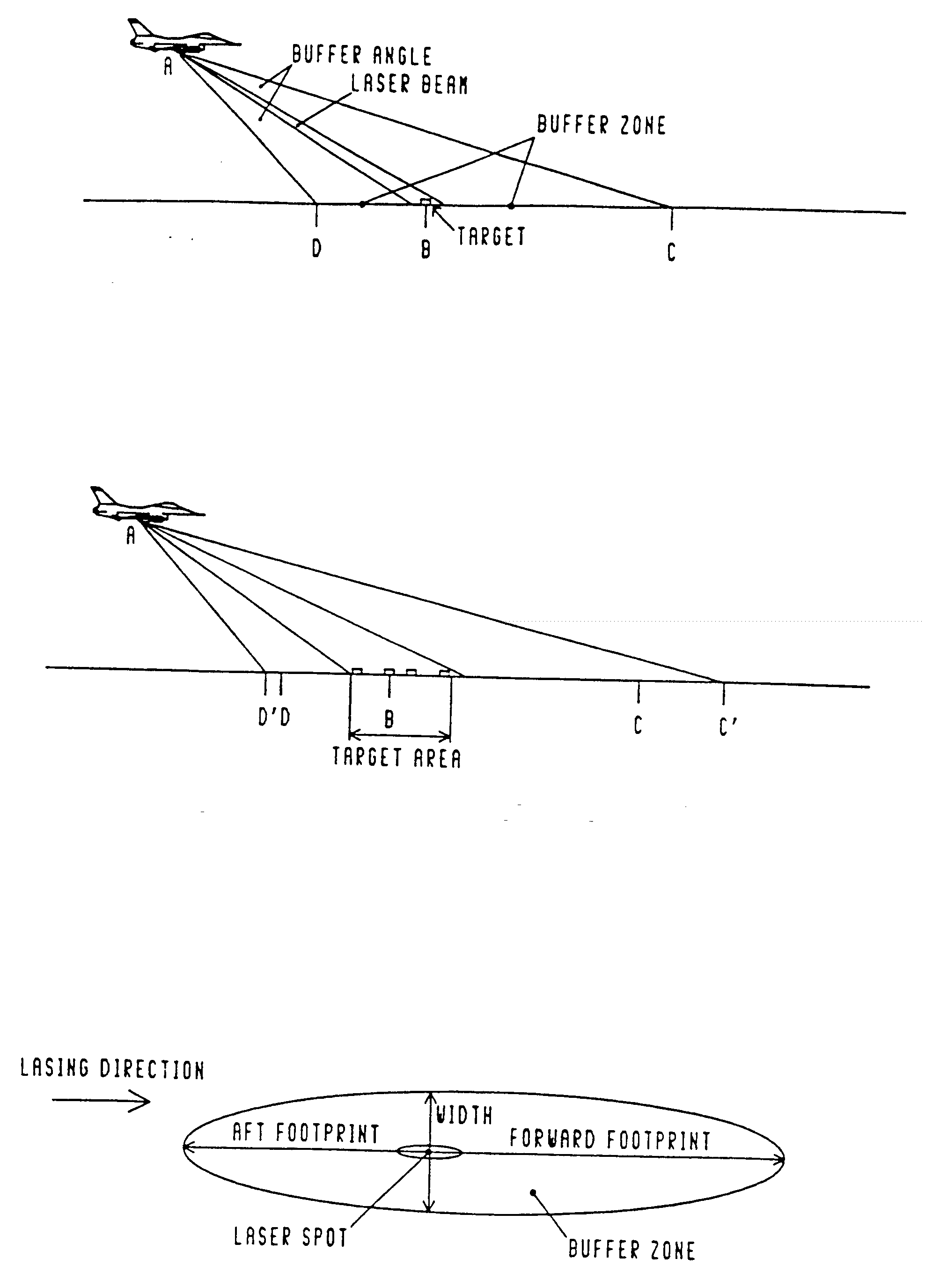
|
Table E-1. Laser Footprint Table For: Pave Spike (Using Vacuum NOHD) Table based on: Flat terrain, Buffer = 2.5 , mrad, Divergence = .35 mrad NOHD= 10000 meters (32900 feet or 5.4 nautical miles) Table values are FOOTPRINT dimensions(feet and meters) |
FOOTPRINT FORWARD - distance beyond target FOOTPRINT AFT - distance from target toward aircraft. FOOTPRINT WIDTH - total width at target. NOTE: -99 Indicates an impossible alt./range combination. |
SLANT RANGE (nautical miles, feet, and meters)
ALTITUDE      FOOTPRINT            1.0 NM        2.0 NM        3.0 NM        4.0 NM        5.0 NM        6.0 NM        7.0 NM        8.0 NM        9.0 NM
(feet)                            6080 ft      12200 ft      18200 ft      24300 ft      30400 ft      36500 ft      42500 ft      48600 ft      54700 ft
                                  1850 m        3700 m        5560 m        7410 m        9260 m       11100 m       13000 m       14800 m       16700 m

 100          FORWARD             1180 ft       5850 ft      14600 ft       8500 ft       2420 ft          0 ft          0 ft          0 ft          0 ft
                                   359 m        1780 m        4440 m        2590 m         737 m           0 m           0 m           0 m           0 m
              AFT                  850 ft       2980 ft       5970 ft       9580 ft      13600 ft      18000 ft      22500 ft      27500 ft      32500 ft
                                   259 m         909 m        1820 m        2920 m        4150 m        5490 m        6900 m        8380 m        9900 m

 200          FORWARD              537 ft       2360 ft       5880 ft       8500 ft       2420 ft          0 ft          0 ft          0 ft          0 ft
                                   164 m         719 m        1790 m        2590 m         731 m           0 m           0 m           0 m           0 m
              AFT                  457 ft      1,700 ft       3570 ft       5960 ft       8780 ft      11900 ft      15400 ft      19200 ft      23100 ft
                                   139 m         518 m        1090 m        1820 m        2680 m        3640 m        4700 m        5840 m        7040 m

 300          FORWARD              348 ft       1480 ft       3540 ft       6720 ft       2420 ft          0 ft          0 ft          0 ft          0 ft
                                   106 m         450 m        1080 m        2050 m         737 m           0 m           0 m           0 m           0 m
              AFT                  312 ft       1190 ft       2550 ft       4330 ft       6480 ft       8940 ft      11700 ft          0 ft          0 ft
                                    95 m         362 m         777 m        1320 m        1970 m        2730 m        3560 m           0 m           0 m

 400          FORWARD              257 ft       1070 ft       2530 ft       4720 ft       2420 ft          0 ft          0 ft          0 ft          0 ft
                                    78 m         328 m         171 m        1440 m         737 m           0 m           0 m           0 m           0 m
              AFT                  237 ft        913 ft       1980 ft       3400 ft       5130 ft       7150 ft          0 ft          0 ft          0 ft
                                    72 m         278 m         604 m        1040 m        1560 m        2180 m           0 m           0 m           0 m

 500          FORWARD              204 ft        845 ft       1970 ft       3630 ft       2420 ft          0 ft          0 ft          0 ft          0 ft
                                    62 m         258 m         600 m        1110 m         738 m           0 m           0 m           0 m           0 m
              AFT                  191 ft        742 ft       1620 ft       2800 ft       4250 ft       5950 ft          0 ft          0 ft          0 ft
                                    58 m         226 m         494 m         852 m        1290 m        1810 m           0 m           0 m           0 m

 600          FORWARD              169 ft        696 ft       1610 ft       2950 ft       2420 ft          0 ft          0 ft          0 ft          0 ft
                                    52 m         212 m         491 m         900 m         738 m           0 m           0 m           0 m           0 m
              AFT                  160 ft        625 ft       1370 ft       2380 ft       3620 ft       5100 ft          0 ft          0 ft          0 ft
                                    49 m         190 m         418 m         724 m        1100 m        1550 m           0 m           0 m           0 m

 700          FORWARD              144 ft        592 ft       1360 ft       2490 ft       2420 ft          0 ft          0 ft          0 ft          0 ft
                                    44 m         180 m         416 m         758 m         738 m           0 m           0 m           0 m           0 m
              AFT                  138 ft        539 ft       1190 ft       2070 ft       3160 ft       4450 ft          0 ft          0 ft          0 ft
                                    42 m         164 m         362 m         630 m         963 m        1360 m           0 m           0 m           0 m

 800          FORWARD              126 ft        515 ft       1180 ft       2150 ft       2420 ft          0 ft          0 ft          0 ft          0 ft
                                    38 m         157 m         361 m         655 m         738 m           0 m           0 m           0 m           0 m
              AFT                  121 ft        475 ft       1050 ft       1830 ft       2800 ft       3960 ft          0 ft          0 ft          0 ft
                                    37 m         145 m         319 m         557 m         854 m        1210 m           0 m           0 m           0 m

              WIDTH                 33 ft         65 ft         98 ft        130 ft        163 ft        195 ft        228 ft        260 ft        293 ft
                                    10 m          20 m          30 m          40 m          50 m          59 m          69 m          79 m          89 m
|
Table E-2. Laser Footprint Table For: Pave Spike (Including Atmospheric Attenuation for Lasing from Altitudes below 1 km MSL Only) Table based on: Flat terrain, Buffer = 2.5 mrad, Divergence = .35 mrad NOHD= 8200 meters (26896 feet or 4.4 nautical miles) Table values are FOOTPRINT dimensions(feet and meters) |
FOOTPRINT FORWARD - distance beyond target. FOOTPRINT AFT - distance from target bard aircraft. FOOTPRINT WIDTH - total width at target. N0TE: -99 indicates an impossible alt./range combination. |
SLANT RANGE (nautical miles, feet, and meters)
ALTITUDE      FOOTPRINT           1.0 NM        2.0 NM        3.0 NM        4.0 NM         5.0 NM       6.0 NM         7.0 NM        8.0 NM       9.0 NM
(feet)                           6080 ft      12200 ft      18200 ft      24300 ft       30400 ft     36500 ft       42500 ft      48600 ft     54700 ft
                                 1850 m        3700 m        5560 m        7410 m         9260 m      11100 m        13000 m       14800 m      16700 m

100           FORWARD            1180 ft       5850 ft       8670 ft       2590 ft          0 ft          0 ft           0 ft          0 ft         0 ft
                                  359 m        1780 m        2640 m         790 m           0 m           0 m            0 m           0 m          0 m
              AFT                 850 ft       2980 ft       5970 ft       9580 ft      13600 ft      18000 ft       22600 ft      27500 ft     32500 ft
                                  259 m         909 m        1820 m        2920 m        4150 m        5490 m         6900 m        8380 m       9900 m

200           FORWARD             537 ft       2360 ft       5880 ft       2590 ft          0 ft          0 ft           0 ft          0 ft         0 ft
                                  164 m         719 m        1790 m         790 m           0 m           0 m            0 m           0 m          0 m
              AFT                 457 ft       1700 ft       3570 ft       5960 ft       8780 ft      11900 ft           0 ft          0 ft         0 ft
                                  139 m         518 m        1090 m        1820 m        2680 m        3640 m            0 m           0 m          0 m

300           FORWARD             348 ft       1480 ft       3540 ft       2590 ft          0 ft          0 ft           0 ft          0 ft         0 ft
                                  106 m         450 m        1080 m         790 m           0 m           0 m            0 m           0 m          0 m
              AFT                 312 ft       1190 ft       2550 ft       4330 ft       6480 ft          0 ft           0 ft          0 ft         0 ft
                                   95 m         362 m         777 m        1320 m        1970 m           0 m            0 m           0 m          0 m

400           FORWARD             257 ft       1070 ft       2530 ft       2590 ft          0 ft          0 ft           0 ft          0 ft         0 ft
                                   78 m         328 m         771 m         790 m           0 m           0 m            0 m           0 m          0 m
              AFT                 237 ft        913 ft       1980 ft       3400 ft       5130 ft          0 ft           0 ft          0 ft         0 ft
                                   72 m         278 m         604 m        1040 m        1560 m           0 m            0 m           0 m          0 m

500           FORWARD             204 ft        845 ft       1970 ft       2590 ft          0 ft          0 ft           0 ft          0 ft         0 ft
                                   62 m         258 m         600 m         790 m           0 m           0 m            0 m           0 m          0 m
              AFT                 191 ft        742 ft       1620 ft       2800 ft       4250 ft          0 ft           0 ft          0 ft         0 ft
                                   58 m         226 m         494 m         852 m        1290 m           0 m            0 m           0 m          0 m

600           FORWARD             169 ft        696 ft       1610 ft       2590 ft          0 ft          0 ft           0 ft          0 ft         0 ft
                                   52 m         212 m         491 m         790 m           0 m           0 m            0 m           0 m          0 m
              AFT                 160 ft        625 ft       1370 ft       2380 ft       3620 ft          0 ft           0 ft          0 ft         0 ft
                                   49 m         190 m         418 m         724 m        1100 m           0 m            0 m           0 m          0 m

700           FORWARD             144 ft        592 ft       1360 ft       2490 ft          0 ft          0 ft           0 ft          0 ft         0 ft
                                   44 m         180 m         416 m         758 m           0 m           0 m            0 m           0 m          0 m
              AFT                 138 ft        539 ft       1190 ft       2070 ft          0 ft          0 ft           0 ft          0 ft         0 ft
                                   42 m         164 m         362 m         630 m           0 m           0 m            0 m           0 m          0 m

800           FORWARD             126 ft        515 ft       1180 ft       2150 ft          0 ft          0 ft           0 ft          0 ft         0 ft
                                   38 m         157 m         361 m         655 m           0 m           0 m            0 m           0 m          0 m
              AFT                 121 ft        475 ft       1050 ft       1830 ft          0 ft          0 ft           0 ft          0 ft         0 ft
                                   37 m         145 m         319 m         557 m           0 m           0 m            0 m           0 m          0 m

              WIDTH                33 ft         65 ft         98 ft        130 ft        163 ft        195 ft         228 ft        260 ft       293 ft
                                   10 m          20 m          30 m          40 m          50 m          59 m           69 m          79 m         89 m
|
Table E-3. Laser Footprint Table For: Pave Tack (Using Vacuum NOHD) Table based on: Flat terrain, Buffer = 2 mrad, Divergence = 0 mrad NOHD= 16000 meters (52480 feet or 8.6 nautical miles) Table values are FOOTPRINT dimensions(feet and meters) |
FOOTPRINT FORWARD - distance beyond target. FOOTPRINT AFT - distance from target bard aircraft. FOOTPRINT WIDTH - total width at target. NOTE: -99 indicates an impossible alt./range combination. |
SLANT RANGE (nautical miles, feet, and meters)
ALTITUDE      FOOTPRINT            1.0 NM        2.0 NM        3.0 NM        4.0 NM        5.0 NM        6.0 NM        7.0 NM        8.0 NM        9.0 NM
(feet)                            6080 ft      12200 ft      18200 ft      24300 ft      30400 ft      36500 ft      42500 ft      48600 ft      54700 ft
                                  1850 m        3700 m        5560 m        7410 m        9260 m       11100 m       13000 m       14800 m       16700 m

100          F0RWARD               841 ft       3900 ft      10500 ft      23000 ft      22100 ft      16000 ft       9950 ft       3870 ft          0 ft
                                   256 m        1190 m        3190 m        7010 m        6740 m        4880 m        3030 m        1180 m           0 m
              AFT                  658 ft       2380 ft       4870 ft       7950 ft      11500 ft      15400 ft      19600 ft      24000 ft      28600 ft
                                   201 m         724 m        1480 m        2420 m        3500 m        4690 m        5960 m        7300 m        8710 m

 200          F0RWARD              393 ft       1680 ft       4060 ft       7800 ft      13300 ft      16000 ft       9950 ft       3870 ft          0 ft
                                   120 m         512 m        1240 m        2380 m        4040 m        4880 m        3030 m        1180 m           0 m
              AFT                  348 ft       1320 ft       2810 ft       4750 ft       7080 ft       9740 ft      12700 ft      15900 ft      19300 ft
                                   106 m         401 m         857 m        1450 m        2160 m        2970 m        3870 m        4850 m        5890 m

 300          F0RWARD              257 ft       1070 ft       2520 ft       4700 ft       7720 ft      11700 ft       9950 ft       3870 ft          0 ft
                                    78 m         327 m         769 m        1430 m        2350 m        3570 m        3030 m        1180 m           0 m
              AFT                  237 ft        911 ft       1980 ft       3390 ft       5120 ft       7130 ft       9400 ft      11900 ft      14600 ft
                                    72 m         278 m         602 m        1030 m        1560 m        2170 m        2860 m        3630 m        4450 m

 400          FORWARD              190 ft        786 ft       1830 ft       3360 ft       5440 ft       8130 ft       9950 ft       3870 ft          0 ft
                                    58 m         240 m         557 m        1020 m        1660 m        2480 m        3030 m        1180 m           0 m
              AFT                  179 ft        696 ft       1520 ft       2630 ft       4010 ft       5620 ft       7460 ft       9500 ft      11700 ft
                                    55 m         212 m         464 m         803 m        1220 m        1710 m        2270 m        2900 m        3580 m

 500          FORWARD              151 ft        621 ft       1430 ft       2620 ft       4200 ft       6220 ft       8720 ft       3870 ft          0 ft
                                    46 m         189 m         437 m         798 m        1280 m        1900 m        2660 m        1180 m           0 m
              AFT                  144 ft        563 ft       1240 ft       2150 ft       3290 ft       4640 ft       6180 ft       7910 ft       9810 ft
                                    44 m         172 m         378 m         656 m        1000 m        1410 m        1880 m        2410 m        2990 m

 600          F0RWARD              126 ft        513 ft       1180 ft       2140 ft       3420 ft       5040 ft       7030 ft       3870 ft          0 ft
                                    33 m         156 m         359 m         653 m        1040 m        1540 m        2140 m        1180 m           0 m
              AFT                  121 ft        473 ft       1040 ft       1820 ft       2790 ft       3950 ft       5280 ft       6780 ft       8430 ft
                                    37 m         144 m         318 m         555 m         852 m        1200 m        1610 m        2070 m        2570 m

 700          FORWARD              107 ft        437 ft       1000 ft       1810 ft       2890 ft       4240 ft       5880 ft       3870 ft          0 ft
                                    33 m         133 m         305 m         553 m         880 m        1290 m        1790 m        1180 m           0 m
              AFT                  104 ft        408 ft        902 ft       1580 ft       2430 ft       3440 ft       4610 ft       5930 ft       7390 ft
                                    32 m         124 m         275 m         481 m         740 m        1050 m        1400 m        1810 m        2250 m

 800          FORWARD               94 ft        381 ft        870 ft       1570 ft       2500 ft       3660 ft       5060 ft       3870 ft          0 ft
                                    29 m         116 m         265 m         479 m         761 m        1110 m        1540 m        1180 m           0 m
              AFT                   91 ft        358 ft        795 ft       1390 ft       2140 ft       3050 ft       4090 ft       5270 ft       6580 ft
                                    28 m         109 m         242 m         424 m         654 m         928 m        1250 m        1610 m        2000 m

              WIDTH                 24 ft         49 ft         73 ft         97 ft        122 ft        146 ft        170 ft        194 ft        219 ft
                                     7 m          15 m          22 m          30 m          37 m          44 m          52 m          59 m          67 m
|
Table E-4. Laser Footprint Table For: Pave Tack (Including Atmospheric Attenuation for Lasing from Altitudes below 1 km MSL Only) Table based on: Flat terrain, Buffer = 2 mrad, Divergence = 0 mrad NOHD= 12000 meters (39360 feet or 6.5 nautical miles) Table values are FOOTPRINT dimensions(feet and meters) |
FOOTPRINT FORWARD - distance beyond target. FOOTPRINT AFT - distance from target toward aircraft. FOOTPRINT WIDTH = total width at target. NOTE: -99 indicates an impossible alt./range combination |
SLANT RANGE (nautical miles, feet, and meters)
ALTITUDE      FOOTPRINT            1.0 NM        2.0 NM        3.0 NM        4.0 NM        5.0 NM        6.0 NM        7.0 NM        8.0 NM        9.0 NM
(feet)                            6080 ft      12200 ft      18200 ft      24300 ft      30400 ft      36500 ft      42500 ft      48600 ft      64700 ft
                                  1850 m        3700 m        5560 m        7410 m        9260 m       11100 m       13000 m       14800 m       16700 m
100 FORWARD 841 ft 3900 ft 10500 ft 15100 ft 8980 ft 2900 ft 0 ft 0 ft 0 ft
256 m 1190 m 3190 m 4590 m 2740 m 885 m 0 m 0 m 0 m
AFT 658 ft 2380 ft 4870 ft 7950 ft 11500 ft 15400 ft 19600 ft 24000 ft 28600 ft
201 m 724 m 1480 m 2420 m 3500 m 4690 m 5960 m 7300 m 8710 m
200 FORWARD 393 ft 1680 ft 4060 ft 7800 ft 8980 ft 2900 ft 0 ft 0 ft 0 ft
120 m 512 m 1240 m 2380 m 2740 m 885 m 0 m 0 m 0 m
AFT 348 ft 1320 ft 2810 ft 4750 ft 7080 ft 9740 ft 12700 ft 15900 ft 19300 ft
106 m 401 m 857 m 1450 m 2160 m 2970 m 3870 m 4850 m 5890 m
300 FORWARD 257 ft 1070 ft 2520 ft 4700 ft 7720 ft 2900 ft 0 ft 0 ft 0 ft
78 m 327 m 769 m 1430 m 2350 m 885 m 0 m 0 m 0 m
AFT 237 ft 911 ft 1980 ft 3390 ft 5120 ft 7130 ft 9400 ft 11900 ft 0 ft
72 m 278 m 602 m 1030 m 1560 m 2170 m 2860 m 3630 m 0 m
400 FORWARD 190 ft 786 ft 1830 ft 3360 ft 5440 ft 2900 ft 0 ft 0 ft 0 ft
58 m 240 m 557 m 1020 m 1660 m 885 m 0 m 0 m 0 m
AFT 179 ft 695 ft 1520 ft 2630 ft 4010 ft 5620 ft 7460 ft 9500 ft 0 ft
55 m 212 m 464 m 803 m 1220 m 1710 m 2270 m 2900 m 0 m
500 FORWARD 151 ft 621 ft 1430 ft 2620 ft 4200 ft 2900 ft 0 ft 0 ft 0 ft
46 m 189 m 437 m 798 m 1280 m 885 m 0 m 0 m 0 m
AFT 144 ft 563 ft 1240 ft 2150 ft 3290 ft 4640 ft 6180 ft 0 ft 0 ft
44 m 172 m 378 m 656 m 1000 m 1410 m 1880 m 0 m 0 m
600 FORWARD 126 ft 513 ft 1180 ft 2140 ft 3420 ft 2900 ft 0 ft 0 ft 0 ft
38 m 156 m 359 m 653 m 1040 m 885 m 0 m 0 m 0 m
AFT 121 ft 473 ft 1040 ft 1820 ft 2790 ft 3950 ft 5280 ft 0 ft 0 ft
37 m 144 m 318 m 555 m 852 m 1200 m 1610 m 0 m 0 m
700 FORWARD 107 ft 437 ft 1000 ft 1810 ft 2890 ft 2900 ft 0 ft 0 ft 0 ft
33 m 133 m 305 m 553 m 880 m 885 m 0 m 0 m 0 m
AFT 104 ft 408 ft 902 ft 1580 ft 2430 ft 3440 ft 4610 ft 0 ft 0 ft
32 m 124 m 275 m 481 m 740 m 1050 m 1400 m 0 m 0 m
800 FORWARD 94 ft 381 ft 870 ft 1570 ft 2500 ft 2900 ft 0 ft 0 ft 0 ft
29 m 116 m 265 m 479 m 761 m 885 m 0 m 0 m 0 m
AFT 91 ft 358 ft 795 ft 1390 ft 2140 ft 3050 ft 4090 ft 0 ft 0 ft
28 m 109 m 242 m 424 m 654 m 928 m 1250 m 0 m 0 m
WIDTH 24 ft 49 ft 73 ft 97 ft 122 ft 146 ft 170 ft 194 ft 219 ft
7 m 15 m 22 m 30 m 37 m 44 m 52 m 59 m 67 m
|
Table E-5. Laser Footprint Table For: Any Laser System with Beam Divergence < 0.5 mrad Table based on: Flat terrain. Buffer = 5 mrad, Divergence = 0 mrad N0HD= 100000 meters (328000 feet or 54.0 nautical miles) Table values are FOOTPRINT dimensions(feet and meters) |
FOOTPRINT FORWARD - distance beyond target. FOOTPRINT AFT - distance from target toward aircraft. FOOTPRINT WIDTH - total width at target. NOTE: -99 indicates an impossible alt./range combination. |
SLANT RANGE (nautical miles, feet, and meters)
ALTITUDE   FOOTPRINT            1.0 NM        2.0 NM        3.0 NM        4.0 NM        5.0 NM        6.0 NM        7.0 NM        8.0 NM        9.0 NM
(feet)                         6080 ft      12200 ft      18200 ft      24300 ft      30400 ft      36500 ft      42500 ft      48600 ft      54700 ft
                               1850 m        3700 m        5560 m        7410 m        9260 m       11100 m       13000 m       14800 m       16700 m

100        FORWARD             2650 ft      18800 ft     188000 ft     304000 ft     298000 ft     292000 ft     285000 ft     279000 ft     273000 ft
                                808 m        5740 m       57200 m       92600 m       90700 m       88900 m       87000 m       85200 m       83300 m
           AFT                 1420 ft       4590 ft       8690 ft      13300 ft      18300 ft      23500 ft      28900 ft      34400 ft      40000 ft
                                432 m        1400 m        2650 m        4060 m        5580 m        7180 m        8820 m       10500 m       12200 m

200        FORWARD             1090 ft       5300 ft      15300 ft      37600 ft      95900 ft     292000 ft     285000 ft     279000 ft     273000 ft
                                332 m        1620 m        4650 m       11500 m       29200 m       88900 m       87000 m       85200 m       83300 m
           AFT                  801 ft       2830 ft       5710 ft       9190 ft      13100 ft      17400 ft      21900 ft      26700 ft      31600 ft
                                244 m         863 m        1740 m        2800 m        4000 m        5300 m        6680 m        8130 m        9630 m

300        FORWARD              685 ft       3090 ft       7950 ft      16500 ft      31200 ft      56500 ft     104000 ft     207000 ft     273000 ft
                                209 m         941 m        2420 m        5040 m        9500 m       17200 m       31500 m       63200 m       83300 m
           AFT                  559 ft       2050 ft       4250 ft       7010 ft      10200 ft      13800 ft      17600 ft      21800 ft      26100 ft
                                170 m         624 m        1290 m        2140 m        3110 m        4200 m        5380 m        6630 m        7950 m

400        FORWARD              499 ft       2180 ft       5380 ft      10600 ft      18600 ft      30500 ft      48300 ft      75300 ft     118000 ft
                                152 m         663 m        1640 m        3230 m        5670 m        9300 m       14700 m       22900 m       36000 m
           AFT                  429 ft       1600 ft       3380 ft       5660 ft       8360 ft      11400 ft      14800 ft      18400 ft      22200 ft
                                131 m         488 m        1030 m        1730 m        2550 m        3480 m        4500 m        5600 m        6770 m

500        FORWARD              393 ft       1680 ft       4060 ft       7800 ft      13300 ft      20900 ft      31500 ft      46000 ft      66000 ft
                                120 m         512 m        1240 m        2380 m        4040 m        6380 m        9590 m       14000 m       20100 m
           AFT                  348 ft       1320 ft       2810 ft       4750 ft       7080 ft       9740 ft      12700 ft      15900 ft      19300 ft
                                106 m         401 m         857 m        1450 m        2160 m        2970 m        3870 m        4850 m        5890 m

600        FORWARD              324 ft       1370 ft       3260 ft       6170 ft      10300 ft      15900 ft      23400 ft      33100 ft      45800 ft
                                 99 m         417 m         995 m        1880 m        3140 m        4850 m        7120 m       10100 m       14000 m
           AFT                  293 ft       1120 ft       2400 ft       4090 ft       6140 ft       8500 ft      11100 ft      14000 ft      17100 ft
                                 89 m         341 m         733 m        1250 m        1870 m        2590 m        3390 m        4270 m        5220 m

700        FORWARD              276 ft       1150 ft       2730 ft       5110 ft       8420 ft      12800 ft      18500 ft      25900 ft      35100 ft
                                 84 m         352 m         832 m        1560 m        2570 m        3910 m        5660 m        7880 m       10700 m
           AFT                  253 ft        971 ft       2100 ft       3600 ft       5420 ft       7530 ft       9910 ft      12500 ft      15400 ft
                                 77 m         296 m         640 m        1100 m        1650 m        2300 m        3020 m        3820 m        4880 m

800        FORWARD              240 ft        999 ft       2340 ft       4350 ft       7120 ft      10800 ft      15400 ft      21200 ft      28400 ft
                                 73 m         304 m         714 m        1330 m        2170 m        3280 m        4690 m        6470 m        8650 m
           AFT                  222 ft        858 ft       1860 ft       3210 ft       4850 ft       6770 ft       8930 ft      11300 ft      13900 ft
                                 68 m         262 m         568 m         977 m        1480 m        2060 m        2720 m        3450 m        4250 m

           WIDTH                 61 ft        122 ft        182 ft        243 ft        304 ft        365 ft        425 ft        486 ft        547 ft
19 m 37 m 56 m 74 m 93 m 111 m 130 m 148 m 167 m
3.3.2.4 Unlevel Terrain. Although actual procedures vary on a case-by-case, the following conditions are presented as common.
3.3.2.4.2 Falling Terrain in Target Area or Hills in Foreground. This condition will result in longer forward buffered footprints and more restrictive conditions.
3.3.2.4.2.1 Foreground Distances. The height, MSL, or above ground level (AGL) of the laser in reference to the target must be determined for all distances between the laser and target.
3.3.2.4.2.2 Distance Beyond Target. The downward sloping ground beyond the target can greatly extend the forward footprint as shown in Figures E-10 and E-11. If flight profiles are not limited, the forward footprint could be as long as the NOHD.
3.3.3 Specular Reflections. Determine if the reflection from still water can enter uncontrolled air space or hit a hill or ship's structure within the NOHD and beyond the restricted boundaries (see Figure E-12). If this or other specular reflectors appear to be a problem, limit the flight profiles, move the target, or restrict more land or airspace. If still water cannot be avoided or flat specular reflecting surfaces in the area of the footprint cannot be removed, then the aircrew, personnel in other aircraft, ground and shipboard personnel, and the surrounding community need to be considered. If the reflectivity of the specular surface is known, the effective NOHD (distance from laser to reflector plus distance of reflected beam to end of hazard zone) can be reduced by (approximately) the square root of the reflection coefficient. See Appendix G for some reflection coefficients. For each altitude of the aircraft and distance from the specular reflector, a new sphere or linear distance must be calculated for the specular reflection into the surrounding area or air space. Use the worst case results.
3.3.5 Ground Personnel, Shipboard Personnel, Other Aircraft, and Surrounding Community. If flat specular surfaces are near the target, the laser beam can be redirected in any direction as shown in Figures E-15 and E-16. The LSDZ should then be extended to a hemisphere or portion of a hemisphere with a distance from the specular reflector equal to the NOHD minus the minimum lasing distance from the laser to specular reflector. As with the cases described previously, natural backstops and terrain may alter the shape of this area. Airspace over the range, personnel on ships superstructure, or land based high structures may be at an unacceptable risk.
3.3.6 Hazard Distances From Various Reflective Surfaces. Reflection distances can be calculated from the information in Appendix G.
For both ground based lasers and airborne lasers, the problem can be broken into two constraints: (1) the buffered footprint does not exceed the available controlled area between the target and the laser (near boundary), and (2) the buffered footprint does not exceed the available controlled area beyond the target (far boundary).
3.4.1 Ground Based Lasers. Determine the ability to keep the buffered laser footprint vertically and horizontally within the restricted boundaries.
3.4.1.1 Vertical Buffer Far Boundary. Addressing the far boundary constraint first, Figure E-17 illustrates the geometry of the problem. First determine the available buffer above and below the target out to the edge of the backstop, where

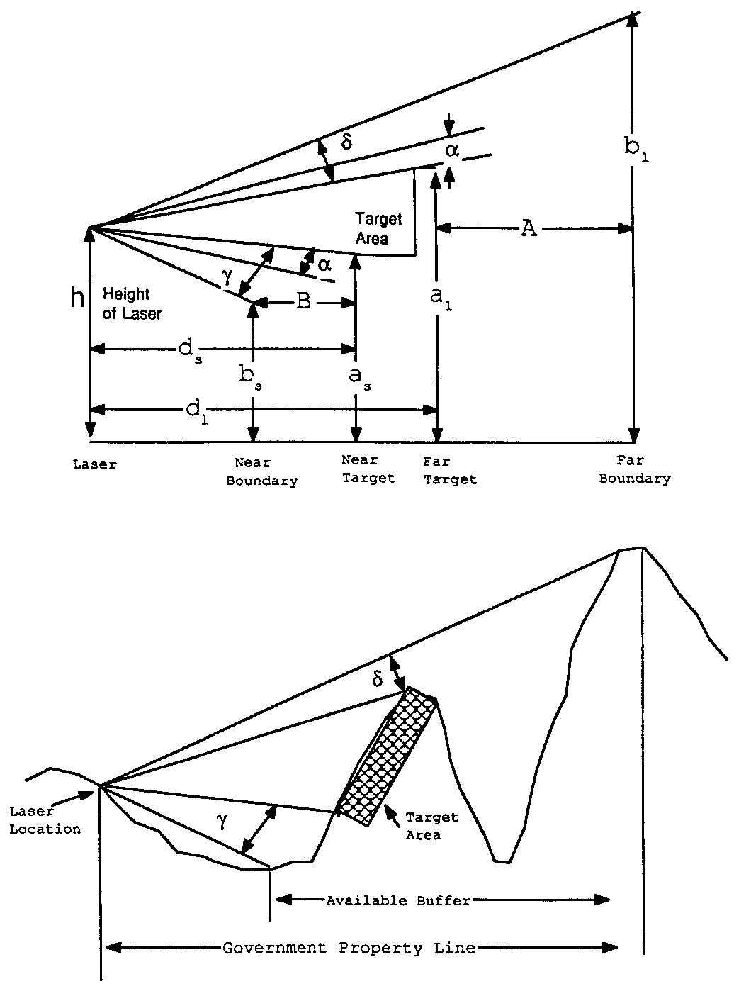
a
= buffer angle plus beam divergence on either side of the laser line of sight (LOS). For systems listed in Table A-1, the beam divergence is extremely small compared to the buffer angle, so the beam divergence may be ignored.d
= available vertical buffer angle between laser LOS to target and laser LOS to backstop.h = altitude of laser
a1 = altitude of far target
bl = altitude of far boundary
dl = horizontal distance on surface from laser to furthest target
A = distance from target to far boundary of LSDZ (backstop)
The angle d may be calculated from
d
= arctan((b1- h)/(d1+ A)) + arctan((h - a1)/(d1))As long as the angle d remains greater than angle a, the beam is safely contained vertically within the designated LSDZ.
3.4.1.2 Vertical Buffer Near Boundary. Similarly for the near boundary,
a
= buffer angle plus beam divergence on either side of the laser LOS. For systems listed in Table A-1, the beam divergence is extremely small compared to the buffer angle, so the beam divergence may be ignored.g
= vertical angle from either side of the laser, LOS to the near edge of LSDZ (backstop) between the laser and the target.h = altitude of laser
as = altitude of nearest target
bs = altitude of near boundary
ds = horizontal distance on surface from laser to nearest target
B = distance from target to near boundary of LSDZ (backstop)
The vertical angle g may be calculated from
g
= arctan((h-bs)/(ds-B)) + arctan((as-h)/ds))As long as the angle g remains greater than the angle a, the beam is safely contained vertically within the designated LSDZ.
AB = arctan((FPN-EBN)/(FPE-EBE)) - arctan((FPN-TN)/(FPE-TE))
where
AB = available buffer angle in radians left and right of target out to the backstop.
FPN = laser firing position north coordinate in meters
EBN = edge of backstop north coordinate in meters
FPE = laser firing position east coordinate in meters
EBE = edge of backstop east coordinate in meters
TN = edge of target north coordinate in meters
TE = edge of target east coordinate in meters
As long as the angle AB is greater than angle a and is negative for the right edge of the backstop and positive for the left edge of the backstop, the beam is safely contained horizontally within the designated LSDZ.
h = Rsin(arcsin((R/A)sin(a)) + a)
the minimum altitude relative to target to keep buffered laser footprint within the near boundary when at slant range R from target is
h = Rsin(arcsin((R/B)sin(a)) - a)
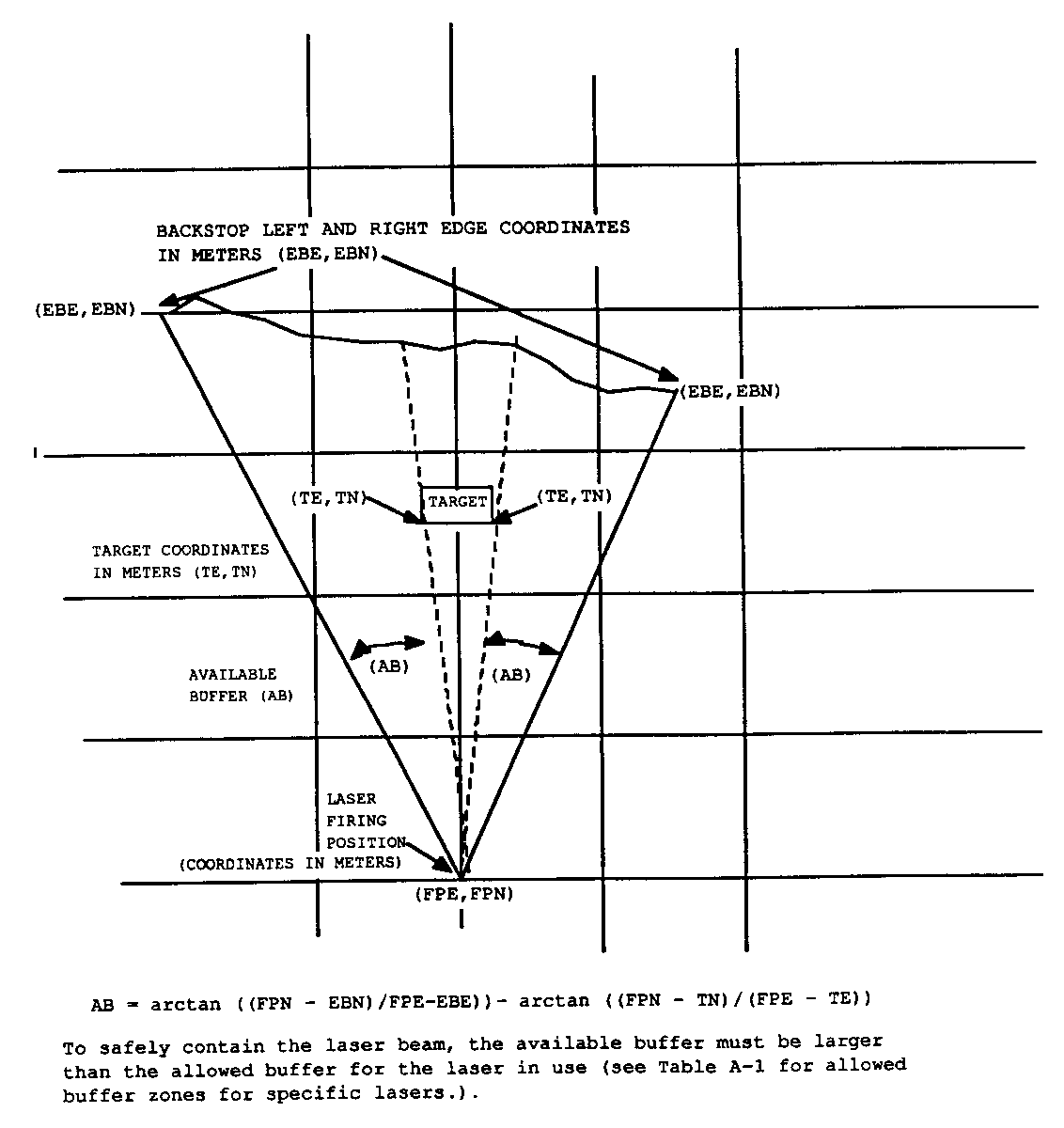
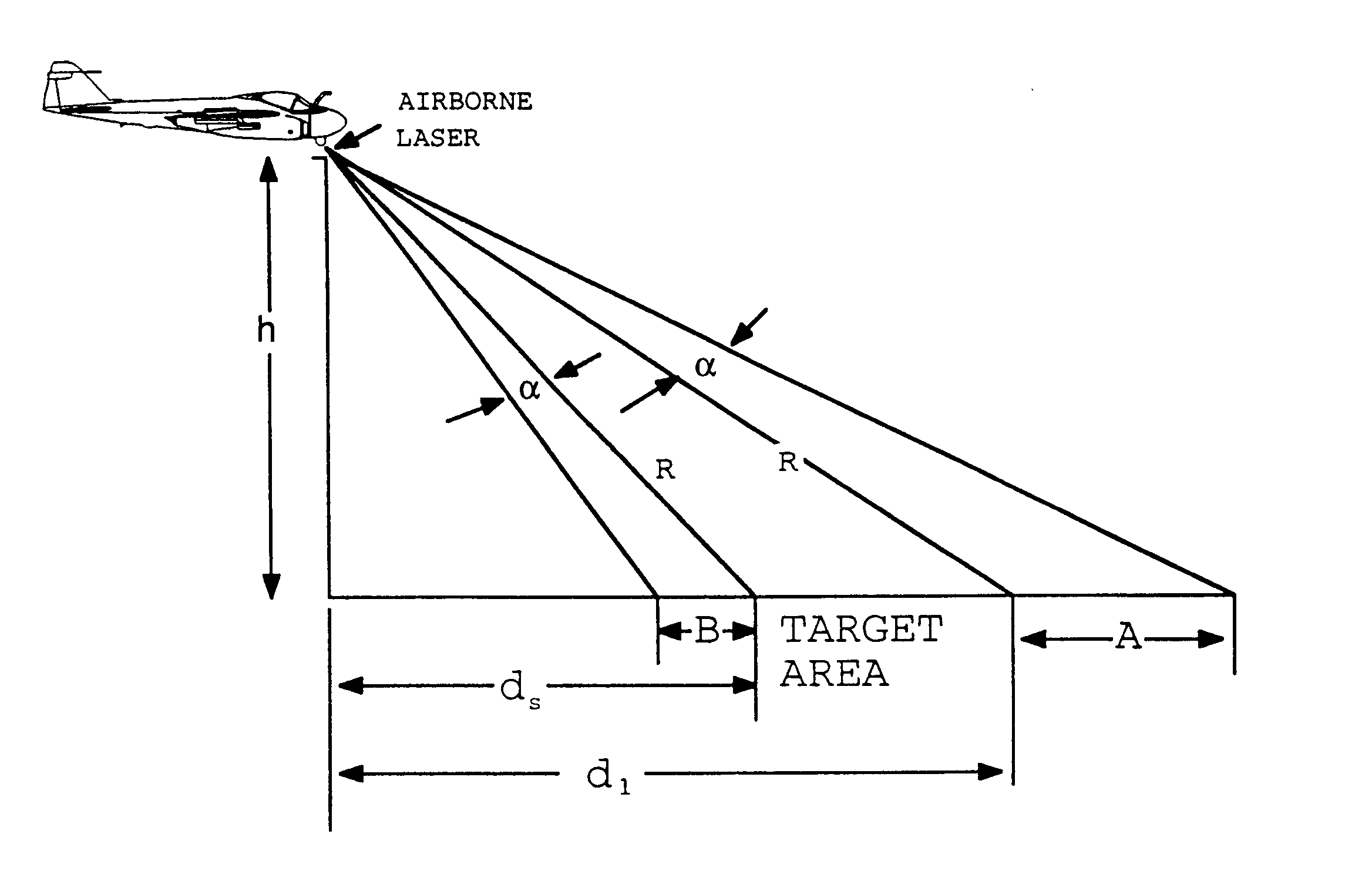
where
R = slant range from laser to target
a
= buffer angle plus beam divergence either side of laser LOS. For systems listed in Table A-1 of Appendix A, the beam divergence is extremely small compared to the buffer angle and hence the beam divergence may be ignored.A = distance from target to far boundary of LSDZ
B = distance from target to near boundary of LSDZ
h = altitude of laser relative to target surface
HL = altitude of laser above Mean Sea Level
HT = height of target above Mean Sea Level
Choose whichever h is the higher number and assign it as the safe altitude for lasing at range R. If altitude is altitude above mean sea level then the required laser altitude is
HL = h + HT
Repeat this calculation for every nautical mile (or fraction of a mile depending on the risk) starting at about 12 nautical miles up to and beyond the target. Then plot the results. Remember as you pass over the target that the far and near boundary definitions reverse. A typical flight profile is plotted in Figure E-20.
s = R x a
s = left hand LSDZ width or right hand LSDZ width
R = slant range from laser to target
a
= assigned buffer angle plus beam divergence on either side of the laser LOS. For systems listed in Table A-1, the beam divergence is small compared to the buffer angle and may be ignored.3.4.2.3.1 Buffered Footprint. See Figure E-2.
HT = altitude of target above mean sea level
h = altitude of laser above target
HL = altitude of laser above mean sea level = h + HT
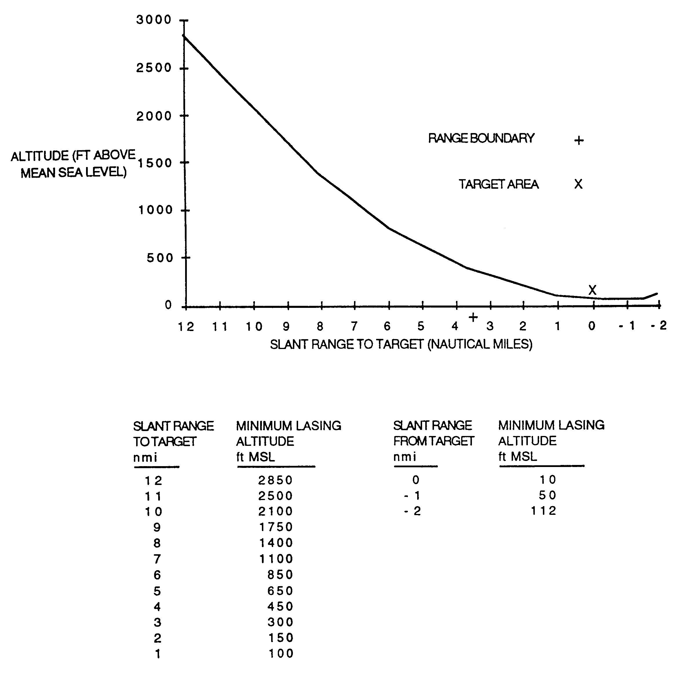
hn = height of near boundary above or below target
hf = height of far boundary above or below target
DN = horizontal distance from target to near boundary
DF = horizontal distance from target to far boundary
N = slant range distance from near edge of near target to edge of near boundary = square root of the sum of the squares of hn and DN
F = slant range distance from far edge of far target to edge of far boundary = square root of the sum of the squares of hf and DF
b
F = declination or elevation angle from horizontal between edge of far target and edge of far boundary = arctan(hf/DF) (positive number for far boundary higher than the target and negative number for far boundary lower than target)b
N = declination or elevation angle from horizontal between edge of near target and edge of near boundary = arctan(hn/DN) (positive number for near boundary lower than target and negative number for near boundary higher than target)hn = height of near boundary above or below target
R = slant range from laser to target
a
= assigned buffer angle plus beam divergence. For systems listed in Table A-1 the beam divergence is small compared to the buffer angle and hence may be ignored.h = Rsin(arcsin((R/F)sin(a)) - bF + a)
and
HL = Rsin(arcsin((R/F)sin(a)) - bF + a) + HT
h = Rsin(arcsin((R/N)sin(a)) - bN - a)
and
HL = Rsin(arcsin((R/N)sin(a)) - bN - a) + HT
Choose whichever h is the higher number and assign it as the safe altitude for lasing at range R. Repeat this calculation for every nautical mile (or fraction of a mile depending on the risk) starting at about 12 nautical miles up to and beyond the target. Then plot the results. Remember as you pass over the target that the far and near boundary definitions reverse. A typical flight profile is plotted on Figure E-20.
3.4.2.3.4 Left and Right Hand LSDZ. The width of the right hand and left hand LSDZ are calculated as
s = R x a
s = left hand LSDZ width or right hand LSDZ width
R = slant range from laser to target
APPENDIX F
DOD LASER RANGE SURVEY CHECKLISTS
APPENDIX F
DOD LASER RANGE SURVEY CHECKLISTS
This appendix provides presurvey, survey, and survey report checklist examples that may be used by tailoring or adding items as needed for local situations such as training operations, research, development, or testing.
Sample checklists are enclosed.
LASER RANGE PRESURVEY CHECKLIST
RANGE/AREA NAME:_________________ DATE: ______________________________
LOCATION (GRID COORDINATES _______________________________________________
ADDRESS:____________________ PLANNED SURVEY DATE:_______________________
____________________________ LAST SURVEY DATE ____________________________
PHONE:(DSN)_________________ PERFORMED BY: ____________________________
(COMM)________________ RANGE POC: ________________________________
USER POCs: __________________________________________________________________
______________________________________________________________________________
DATA COLLECTION
DOCUMENTS
RANGE SOP _______________________________
RANGE LASER DIRECTIVES _________________
OLD SURVEY REPORT _____________________
MAPS OF
RANGE BOUNDARIES _________________ TOPOGRAPHY __________
RESTRICTED AIR SPACE ______________ TGT LOCATIONS ________
LASER OPERATING LOCATIONS _______
TYPES OF LASER OPERATIONS
AIRBORNE LASER OPERATIONS ______________
GROUND BASED LASER OPERATIONS _________
SHIP MOUNTED LASER OPERATIONS _________
SYSTEMS TO BE USED ON RANGE
TRAM_____ LTD______ MULE_____ LANTIRN______ NOS ______
LD-82_____ GVLLD___ M60A2 ____ PAVE TACK____ GVS-5_____
M60A3____ M1A1_____ M551A1____ PAVE SPIKE____ MILES_____
TADS_____ LAAT_____ CLD ______ PAVE KNIFE____ F/A-18_____
MMS______ OTHERS (LIST)
___________________________________________________________
TARGET NAME GRID COORDINATES
1.________________________ ___________________________________
2.________________________ ___________________________________
3.________________________ ___________________________________
4.________________________ ___________________________________
5.________________________ ___________________________________
6.________________________ ___________________________________
7.________________________ ___________________________________
8.________________________ ___________________________________
9.________________________ ___________________________________
10._______________________ ___________________________________
LASER OPERATOR/FIRING POSITIONS GRID COORDINATES
FOR TARGET #?
1.________________________ ___________________________________
2.________________________ ___________________________________
3.________________________ ___________________________________
4.________________________ ___________________________________
5.________________________ ___________________________________
6.________________________ ___________________________________
7.________________________ ___________________________________
8.________________________ ___________________________________
9.________________________ ___________________________________
10._______________________ ___________________________________
FORWARD OBSERVER POSITIONS GRID COORDINATES
FOR TARGET #?/LASER #?
1.________________________ ___________________________________
2.________________________ ___________________________________
3.________________________ ___________________________________
4.________________________ ___________________________________
5.________________________ ___________________________________
6.________________________ ___________________________________
7.________________________ ___________________________________
8.________________________ ___________________________________
9.________________________ ___________________________________
10._______________________ ___________________________________
A. Does the range have established run in headings for aircraft?
Yes ____ No ____
If Yes, what are they?
______________________________________________________________________________
______________________________________________________________________________
______________________________________________________________________________
B. Will more targets be added?
Yes ____ No ____
If yes, where? (grid coordinates)
______________________________________________________________________________
______________________________________________________________________________
C. Are there manned positions on the range?
Yes ____ No ____
If yes, where? (grid coordinates)
______________________________________________________________________________
______________________________________________________________________________
______________________________________________________________________________
D. Are there any conditions off the range that need to be addressed?
Yes ____ No ____
If yes, what?
______________________________________________________________________________
______________________________________________________________________________
______________________________________________________________________________
______________________________________________________________________________
E. Any other changes ____________________________________________________________
______________________________________________________________________________
______________________________________________________________________________
______________________________________________________________________________
______________________________________________________________________________
F. Comments __________________________________________________________________
______________________________________________________________________________
______________________________________________________________________________
______________________________________________________________________________
______________________________________________________________________________
______________________________________________________________________________
REVIEW OF RANGE SOP and/or LASER SAFETY INSTRUCTION
Does SOP or Laser Safety Instruction specify:
(a) Permissible aircraft flight profiles and run-in headings for specified targets or target areas. Yes__ No__
(b) Permissible ships headings and safe firing zones for specified targets or target areas.
Yes__ No__
(c) Permissible ground based laser operating positions and/or areas for specified targets or target areas. Yes__ No__
Yes__ No__
(e) Operating personnel locations (indicating those requiring eye protection). Yes__ No__
(f) Types of surveillance to be used to ensue a clear range. Yes__ No__
(g) Radio frequencies for communication where appropriate.
___________________________________________________________________________
(h) Firing log/schedule is kept by the range officer in accordance with DOD safety and health record keeping regulations. Yes__ No__
(i) Laser systems will not be activated until the target has been positively identified.
Yes__ No__
(j) All class 3 and 4 lasers shall not be directed above the horizon unless coordinated with all DOD components including US Space Command ((DSN 268-4496, (719)474-4496)) and regional service rep to FAA when lasing outside restricted air space. Has coordination been completed? Yes__ No__
(k) For ground based lasers, all unprotected personnel must remain behind the laser operator. Are these instructions in place? Yes__ No__
(l) Requirement that personnel in other aircraft in the restricted cone around the laser line of sight have eye protection of the proper wavelength and optical density as specified in appendix A of the DOD Laser Range Safety Manual for the specific system or as approved by the laser safety specialists for that DOD component. Yes__ No__
(m) Are there specific written requirements for prebriefing all participants in laser exercises to ensure that remote or wingman laser designators are not located within the field of detection of weapons systems or sensors (for example, laser guided munitions, laser spot trackers, NVGs). All tactics must be planned to ensure that the angle between the laser designator and laser guided munitions is such that the munitions cannot home on the laser source or scattered radiation from the laser platform. Yes__ No___
RANGE LASER SITE SURVEY
1. Laser Safety Officer
_______________________________________________________________
Address
_______________________________________________________________
Phone (DSN)
_______________________________________________________________
2. Is there a laser safety officer on range during laser operations?
Yes ____ No ____
3. Have all of the range personnel involved with laser operations had laser safety training?
Yes ____ No ____
4. Is there a medical surveillance program in place? Yes ____ No ____
5. For lasers not listed in Appendix A, have all of the lasers being used on the range been evaluated by the specific service agency in Chapter 1, subparagraph 1.2.1? Yes ____ No ____
5. a. Does the range laser safety officer have
(1) safety data Yes ____ No ____
(2) procedural information from operational manuals Yes ____ No ____
(3) data on completed recommended actions in the evaluation report from the service agency? Yes____ No ____
5. b. Has the range laser safety officer been provided with adequate planned tactics to ensure laser employment in compliance with range instructions? Yes____ No____
6. Is the range adequately controlled to prevent unauthorized entry? Yes ____ No ____
7. Are laser warning signs posted at the range boundaries and at the entrance?
Yes ____ No ____
8. Where necessary, are there barricades with laser warning signs? Yes ____ No ____
9. If necessary, are the laser warning signs multilingual? Yes ____ No ____
10. Are the targets made of a non-reflecting material for the laser wavelengths being used on the ranges? Yes ____ No ____
11. Are the target and target areas free of specular reflectors? Yes ____ No ____
12. Is there a protective eyewear training, inspection and replacement program in place?
Yes ____ No ____
13. Are all of the personnel who must be on the range during laser operations equipped with the proper eye protection? Yes ____ No ____
14. Is a laser operations log or schedule containing the date, time, and heading of all laser operations being kept? Yes ____ No ____
15. Is there two-way communication between the range laser safety officer, laser system operators, and range personnel? Yes ____ No ____
16. Describe the surveillance of the range.
RANGE SURVEY REPORT
Note: This report may require sign-off by the Service Laser Safety Authority.
RANGE/AREA NAME:
SURVEY SUMMARY
Date Survey was completed ______________________________________________________
Applicable Regulations __________________________________________________________
Range controlled by ____________________________________________________________
Survey completed by (Name/Organization)
_____________________________________________________________________________
Dates of operations for which survey is valid _________________________________________
Other Pertinent Information ______________________________________________________
SURVEY RESULTS
1. Degree of compliance with applicable regulations ______________________________________________________________________________
______________________________________________________________________________
2. Safety deficiencies that must be corrected before approving range for laser use:
______________________________________________________________________________
______________________________________________________________________________
______________________________________________________________________________
RECOMMENDED ACTIONS
1. Corrective actions for existing deficiencies
______________________________________________________________________________
______________________________________________________________________________
______________________________________________________________________________
2. Ground Laser Restrictions - Description of Laser Surface Danger Zones (LSDZ)
______________________________________________________________________________
______________________________________________________________________________
______________________________________________________________________________
3. Aircraft Mounted Lasers - Description of Laser Surface Danger Zones (LSDZ)
______________________________________________________________________________
______________________________________________________________________________
______________________________________________________________________________
4. Recommended operating procedures/range regulations
______________________________________________________________________________
______________________________________________________________________________
______________________________________________________________________________
5. Recommended laser eye protection
______________________________________________________________________________
______________________________________________________________________________
______________________________________________________________________________
6. Controls for protection from reflected laser beams
______________________________________________________________________________
______________________________________________________________________________
______________________________________________________________________________
7. Recommended Training
______________________________________________________________________________
______________________________________________________________________________
______________________________________________________________________________
8. Recommended prebriefs for
(1) laser users ____________________________________________________________
________________________________________________________________________
(2) laser range personnel _____________________________________________
________________________________________________________________________
APPENDIX G
SPECULAR REFLECTION
SPECULAR REFLECTION
This appendix provides guidance information on specular reflection hazards.
2.0 Applicable Documents
Van De Merwe, Willem P. and Wesley J. Marshall. "Hazardous Ranges of Laser Beams and Their Reflections from Targets." Applied Optics, vol. 25, no. 5, 1 March 1986.
3.0 Specular Reflection Characteristics
The amount of laser energy reflected from a specular surface and the divergence of the reflected laser beam are dependent on
3.2 Hazardous Ranges of Reflected Laser Beam. The amount of reflected laser energy and the resultant hazard distance from a specular reflector are dependent on the factors provided in Paragraph 3.0.
A specular reflector cross section that is smaller than the cross section of the incident laser beam will only reflect a proportional amount of the laser energy. With small size reflectors, diffraction effects may also be present, resulting in a larger divergence of the laser beam.
Normally a pane of glass will reflect from both the front and back surface; however, the reflected beams are seldom co-linear.
Curved specular reflectors (see Table 6-1) will diverge most laser beams, so they generally present no hazard beyond a few meters from the reflector. For this reason, personnel in laser restricted areas should wear laser eye protection with curved lenses.
3.2.1 Reflection from Reflector Larger Than Cross Section of Incident Laser Beam. Figures 6-7 and G-1 show possible laser reflection hazards from standing water, while Figure G-2 depicts the possible laser reflection hazard from specularly reflecting objects in random orientations. Shown in Figure G-3 is a worst case example of reflectance from both the front and back surfaces of a flat glass plate. Figures G-4 and G-5 show values of reflectance for fresh and salt-water surfaces. In ascertaining the hazardous range of the reflective laser energy, the second surface reflections are usually ignored for distances beyond a few meters from the reflector. Neglecting second surface reflections, the following equation may be used to determine the hazardous range of reflected laser energy in situations similar to those shown in Figure 6-7.
NOHR = H2/cos() = NOHD x (%P x R|| + %N x R)½ - H1/cos()
= NOHDx[%P(tan2(-'))/(tan2(+'))+%N(sin2(-'))/(sin2(+'))]½ - H1/cos()
where
NOHR = Nominal Ocular Hazard Distance from Reflector
H1 = altitude of laser
H2 = altitude of observer viewing reflected laser beam
= angle incident and reflected laser beam makes with a line perpendicular to the reflecting surface (angle of incidence) = arctan(D1/H1) for a flat reflector on flat ground
D1 = horizontal distance from laser to reflector
' = angle of refracted beam in a reflecting media = arcsin(/n)
n = index of refraction of reflecting media
%P = fraction of laser beam polarized parallel to the plane of incidence
%N = fraction of laser beam polarized perpendicular to plane of incidence
NOHD = Nominal Ocular Hazard Distance (see Table A-1 for typical distances)
R|| = Parallel polarization reflection coefficient = (tan2(-'))/(tan2(+'))
R = Perpendicular polarization reflection coefficient = (sin2(-'))/(sin2(+'))
Figure G-2
. LSDZ with specular reflective target - side view.
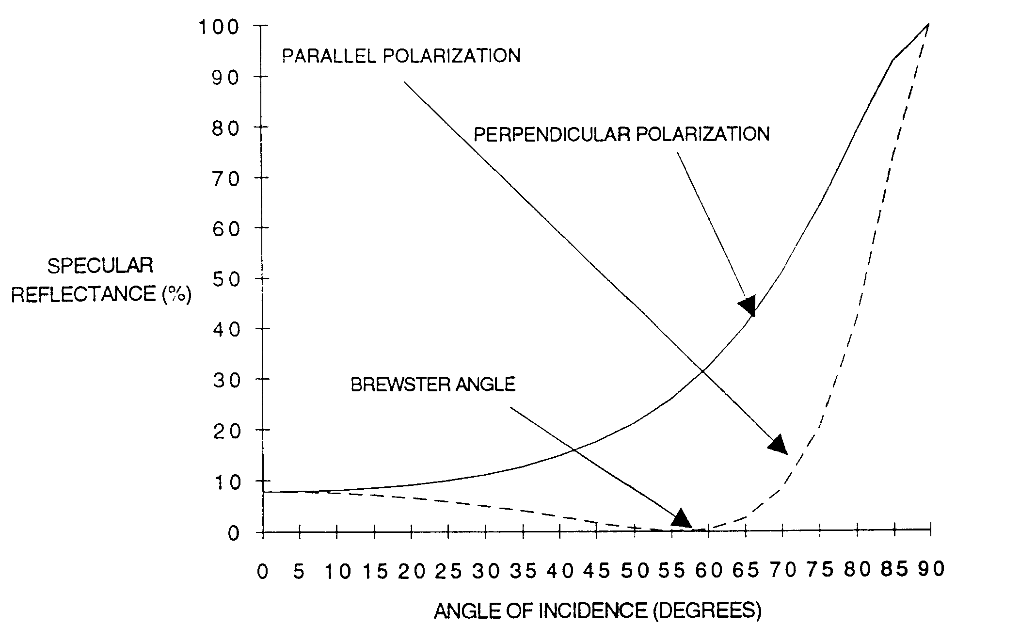
Figure G-3
. Specular reflectance from both surfaces of plate glass (index of refraction = 1.5).
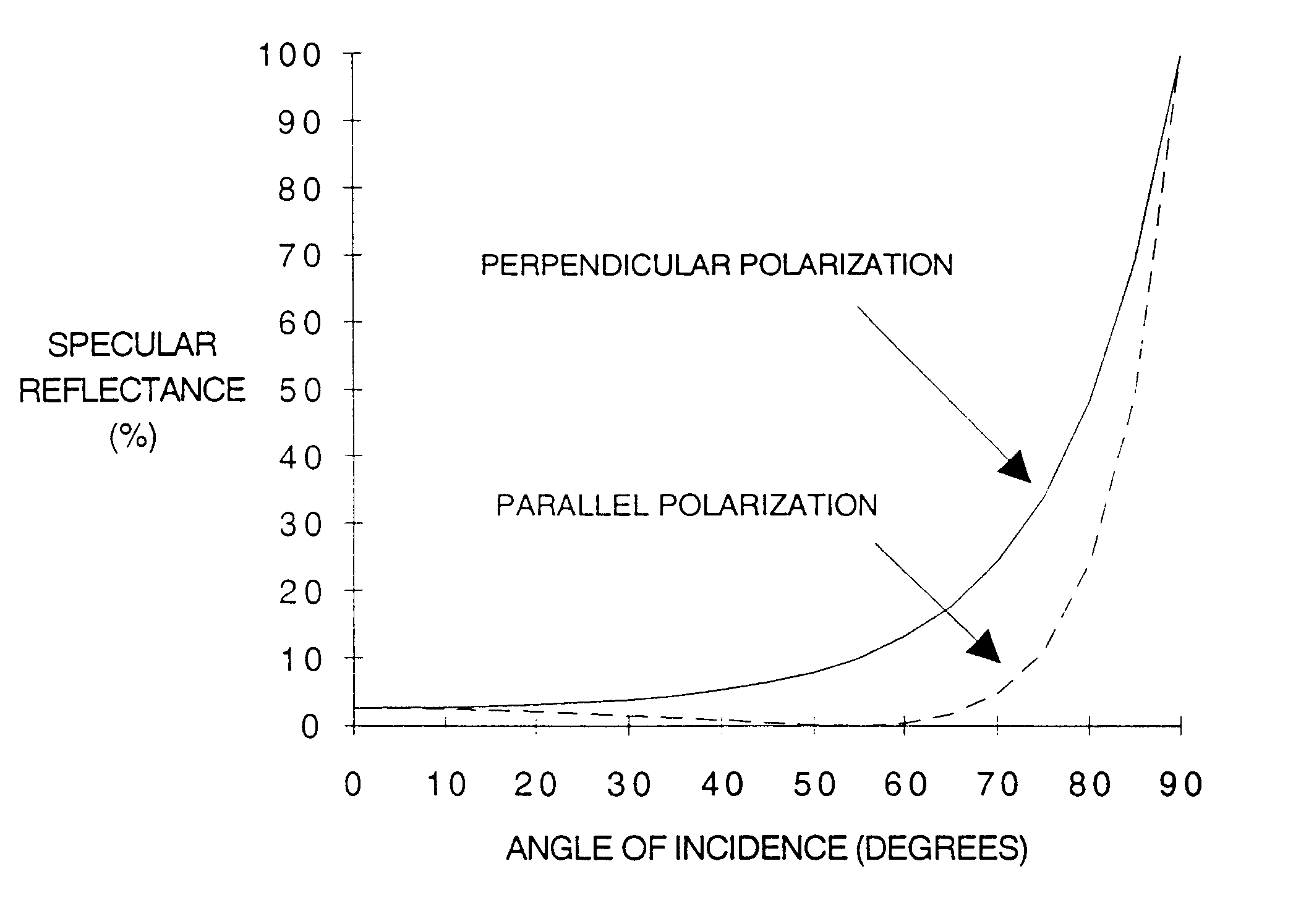
Figure G-
4. Specular reflectance from sea water (index of refraction = 1.378).
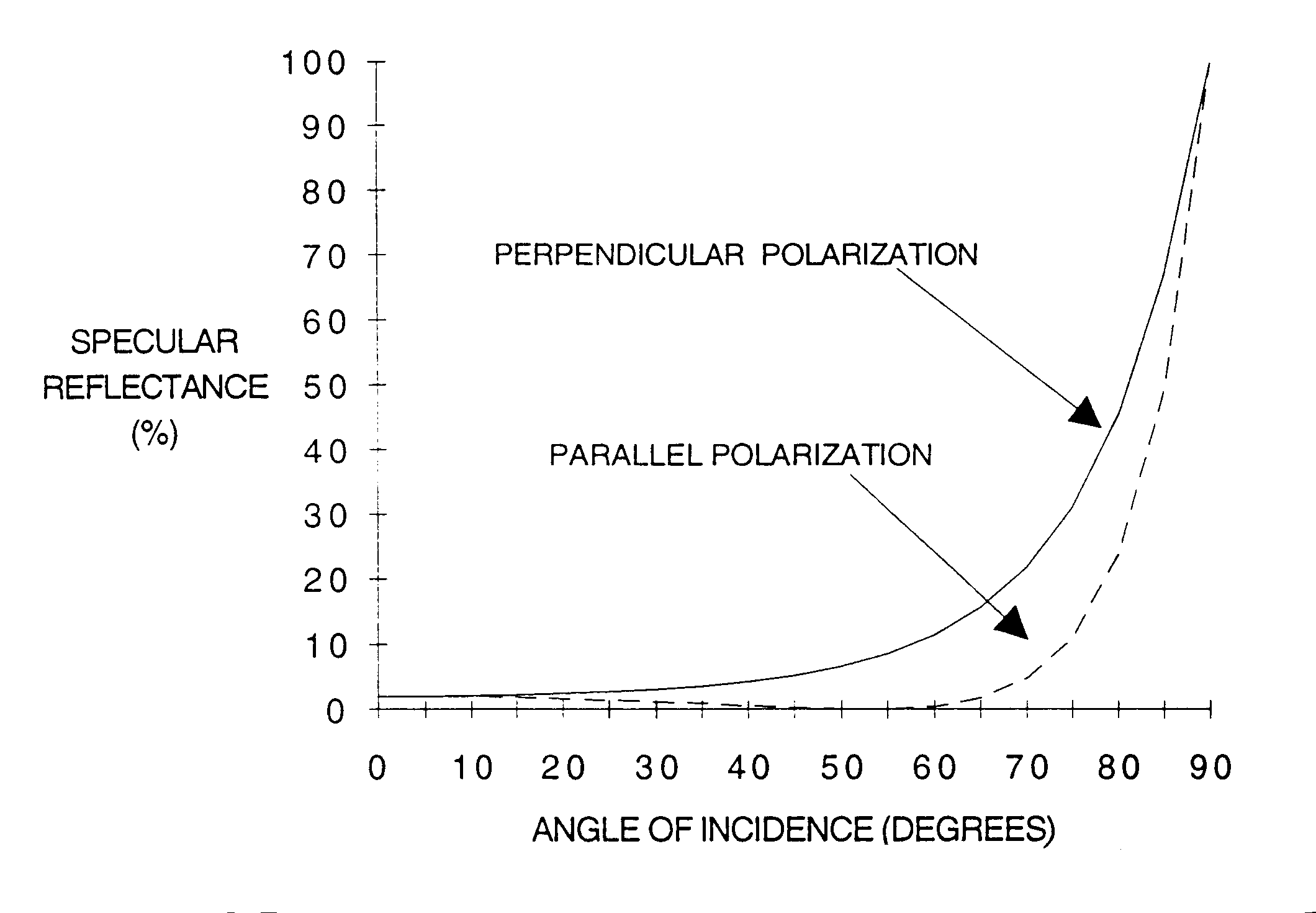
Figure G-5
. Specular reflectance from fresh water (index of refraction =1.33).If the fractions of the laser beam polarizations are not known, choose the highest reflectivity for the given angle of incidence. Typical values are given in Tables G-1 through G-3. Calculate the value of NOHR for various values of D1 and . Choose the worst case NOHR to restrict airspace, ships, vehicles or projecting land masses.
NOHR = H2/cos() = NOHD x (%P x R|| + %N x R)½(RA/LA)½ - H1/cos()
= NOHDx[%P(tan2(-'))/(tan2(+'))+%N(sin2(-'))/(sin2(+'))]½ x (RA/LA)½ - H1/cos()
where
RA = cross sectional area of the reflector
LA = cross sectional area of the incident laser beam
NOHR = Nominal Ocular Hazard Distance from reflector
H1 = altitude of laser
H2 = altitude of observer viewing reflected laser beam
= angle incident and reflected laser beam makes with a line perpendicular to the reflecting surface (angle of incidence)= arctan(D1/H1) for a flat reflector on flat ground.
D1 = horizontal distance from laser to reflector
' = angle of refracted beam in a reflecting media = arcsin(/n)
n = index of refraction of reflecting media
%P = fraction of laser beam polarized parallel to plane of incidence
%N = fraction of laser beam polarized perpendicular to plane of incidence
NOHD = Nominal Ocular Hazard Distance (see Table A-1 for typical distances)
R|| = Parallel polarization reflection coefficient = (tan2(-'))/(tan2+'))
R = Perpendicular polarization reflection coefficient = (sin2(-'))/(sin2(+'))
If the fractions of the laser beam polarization’s are not known, choose the highest reflectivity for the given angle of incidence. Typical values are given in Tables G-1 through G-3. Calculate the value of NOHR for various values of D1 and . Choose the worst case NOHR to restrict airspace, ships, vehicles, or projecting land masses. Table G-4 gives the reflectivity of shiny metal.
|
TABLE G-1. REFLECTIVITY OF GLASS AT VARIOUS ANGLES OF INCIDENCE |
|
MATERIAL – GLASS |
|
APPROX. INDEX OF REFRACTION AT WAVELENGTHS 0.3 TO 2 MICRONS = 1.55 |
|
ANGLE OF REFLECTIVITY |
|
INCIDENCE PERPENDICULAR PARALLEL |
|
(DEGREES) POLARIZATION POLARIZATION |
|
0 0.0465 0.0465 |
|
10 0.0484 0.0447 |
|
20 0.0545 0.0391 |
|
30 0.0664 0.0299 |
|
40 0.0877 0.0175 |
|
50 0.1254 0.0046 |
|
60 0.1935 0.0012 |
|
70 0.3199 0.0400 |
|
80 0.5574 0.2334 |
|
90 1.0 1.0 |
|
TABLE G-2. REFLECTIVITY OF FRESH WATER AT VARIOUS ANGLES OF INCIDENCE |
|
MATERIAL – FRESH WATER |
|
APPROX. INDEX OF REFRACTION AT WAVELENGTHS 0.3 TO 2 MICRONS = 1.33 |
|
ANGLE OF REFLECTIVITY |
|
INCIDENCE PERPENDICULAR PARALLEL |
|
(DEGREES) POLARIZATION POLARIZATION |
|
0 0.0201 0.0201 |
|
10 0.0210 0.0191 |
|
20 0.0241 0.0164 |
|
30 0.0305 0.0117 |
|
40 0.0426 0.0057 |
|
50 0.0660 0.0006 |
|
60 0.1139 0.0044 |
|
70 0.2180 0.0473 |
|
80 0.4552 0.2387 |
|
90 1.0 1.0 |
|
TABLE G-3. REFLECTIVITY OF SEA WATER AT VARIOUS ANGLES OF INCIDENCE |
|
MATERIAL - SEA WATER |
|
APPROX. INDEX OF REFRACTION AT WAVELENGTHS 0.3 TO 2 MICRONS= 1.378 |
|
ANGLE OF REFLECTIVITY |
|
INCIDENCE PERPENDICULAR PARALLEL |
|
(DEGREES) POLARIZATION POLARIZATION |
|
0 0.0253 0.0253 |
|
10 0.0264 0.0241 |
|
20 0.0302 0.0207 |
|
30 0.0378 0.0151 |
|
40 0.0521 0.0078 |
|
50 0.0790 0.0010 |
|
60 0.1324 0.0037 |
|
70 0.2433 0.0467 |
|
80 0.4826 0.2403 |
|
90 1.0 1.0 |
|
TABLE G-4. REFLECTIVITY OF SHINY METAL |
|
MATERIAL – SHINY METAL (SILVER) AT ALL ANGLES OF INCIDENCE |
|
WAVELENGTH REFLECTIVITY |
|
(Microns) |
|
0.45 0.88 |
|
0.50 0.90 |
|
0.55 0.915 |
|
0.60 0.927 |
|
0.65 0.935 |
|
0.70 0.941 |
|
0.80 0.951 |
|
0.90 0.96 |
|
1.0 0.965 |
|
2.0 0.979 |
APPENDIX H
SEPARATE TARGET (SEPTAR)
AND SHIP TOWED TARGET OPERATIONS
APPENDIX H
SEPARATE TARGET (SEPTAR)
AND SHIP TOWED TARGET OPERATIONS
This appendix provides safety guidance on SEPTAR and ship towed target operations.
2.0 Applicable Documents
US Navy E0410-BA-GYD-010, Technical Manual Laser Safety
NATO STANAG 3606, Evaluation and Control of Laser Hazards
3.0 SEPTAR Operations
SEPTARs may be used for A-6E TRAM, OV-10D NOS, F-111F PAVE TACK, and PAVE SPIKE laser operations in open restricted areas provided
Figure H-1. SEPTAR operations area and buffer zone.
4.0 Ship Towed Target Operations
Ship towed target operations as shown in Figure H-2 shall abide by the following:
4.1 The target shall be towed no closer than 1000 feet from the towing ship.
4.2 All laser operations shall be conducted on incoming headings of 60 to 90o and 260 to 300o relative to towing ship's heading. If lasing back at the target is required, after passing over it, the outgoing heading shall be in the zones specified above for the incoming headings (see Figure H-2).
4.3 Laser operation shall not be initiated until the laser operator has identified the target under the reticle on the display, and the pilot has identified the target through the optical gun sight.
4.4 Laser operation must cease if the system is not properly tracking the target.
4.9 Viewing of the target with optical aids from the towing ship or from other ships and aircraft outside of the laser beam hazard control zone described above is permitted.
4.10 Targets shall be non-specular.
4.11 A log of the date, time, and heading of all laser firings must be kept.
Figure H-2. Zones relative to towing ship's heading in which laser operations are permitted
for A-6E TRAM, OV-10D NOS, F111-PAVE TACK, and PAVE SPIKE.
APPENDIX I
FOR SPACE DIRECTED LASERS
APPENDIX I
SATELLITE SAFETY PROCEDURES FOR SPACE DIRECTED LASERS
These guidelines establish the Space Control Center (SCC) Laser Clearinghouse (LCH) procedures.
USCINCSPACE OPLAN 3400.90 page iii (classified secret)
Joint Strategic Capability Plan, paragraph g(2) (a)7. USCINCSPACE will "Disseminate information relating to and provide measures for protecting vital US and allied space systems from interference by collision, directed energy, anti-satellite, nuclear detonation, sabotage, or electronic warfare."
Derivation and Use of the SPADOC Laser Clearinghouse Threshold Curve, June 1983, SAIC. (classified secret)
3.0 Definitions for Space-Directed Laser Emissions
Accidental Illumination - Laser illumination of a satellite payload which was not the intended target, and/or the operation of a laser outside of LCH/PA windows provided by the SCC.
Beam Divergence Half Angle - A parameter which describes the angular spread of a laser beam measured from the beam’s center out to the point where intensity falls to 37 percent of its original value. Typically measured in radians.
Damage - Any physical impairment, either temporary or permanent, of the normal operating capability of a satellite.
DOD Components - A term meaning collectively the Office of the Secretary of Defense, the Joint Chiefs of Staff, the Unified and Specified Commands, the Military Departments, and the Defense Agencies (including national laboratories).
Jitter Angle - The factor which accounts for the mechanical pointing inaccuracies of the laser. The angle, from beam center, in which the beam is located with 96.6 percent probability (2 sigma).
Laser Clearinghouse - A function within USCINCSPACE/SCC which maintains the laser facility data base, receives laser facility emission requests determines waiver status, sends approval/ denial/restrictions to the laser facilities, and processes accidental illumination information.
Laser Damage Threshold - A predetermined level of laser intensity designed to protect satellite sensor material from damage.
Laser Facility - The laser device, supporting system and equipment, tracking mechanism, personnel, building and platform.
Output Aperture Diameter - The beam diameter at the emitter aperture (meters).
Predictive Avoidance Windows - Time intervals generated by SCC allowing a laser to safely conduct space-directed operations without fear of accidentally illuminating satellites.
Payload - The portion of a satellite that contains instrumentation and recording devices, transmitters and receivers, and related support equipment.
Radiant Intensity - The strength of a laser emission at the facility in units of power per solid angle, usually in watts per steradian.
Relative Intensity (IREL) - Accounts for thermal blooming. This factor is defined as the ratio of the actual (experimental) intensity compared to that obtained by a perfect beam (theoretical).
Satellite - Any man-made object in earth orbit.
Satellite Owner/Operator - The agency, unit, company, or other organization responsible for the operation of an orbiting satellite and its command, control, communication, and data utilization.
SCC - Space Control Center (formerly SPADOC) located inside Cheyenne Mountain in Colorado Springs, Colorado.
Strehl Beam Quality Factor - Measures the imperfections within the laser. The factor is equal to the square root of the theoretical power divided by the observed power at a given point.
Target - The satellite which is the intended object of laser illumination.
USCINCSPACE - Commander-in-Chief United States Space Command.
USSPACECOM - United States Space Command.
Waiver - Written permission from JCCDOA granting a laser facility permission to freely operate a space directed laser without the need for safe firing windows
4.1 The Commander in Chief, United States Space Command (USCINCSPACE) is the executive agent for Laser Clearinghouse and, acting through the SCC, is directed by the Joint Strategic Capability Plan to authorize the emission of laser radiation from all DOD or DOD sponsored lasers that have the potential of interfering with, degrading, or damaging any United States or foreign satellite.
4.2 These guidelines apply to all space directed DOD laser facilities, either land based, sea based, airborne, or space based; mobile or fixed including those owned, operated, or controlled by DOD components or by agencies or contractors under the auspices of DOD components. (NOTE: U. S. SPACECOM Laser Clearinghouse is only concerned with lasers which are intentionally directed towards space, that is, lasers used for atmospheric research, satellite analysis, astronomical research, and Ballistic Missile Defense testing.). These guidelines apply to United States non-DOD satellite owner/operators (O/Os) by agreement with the SCC. These guidelines do not apply to allied or foreign satellite O/Os. (If there is an interest in lasing a non-United States satellite, contact the SCC for special procedures.)
4.3 These guidelines specify the responsibilities and procedures for
5.3 Facilities operating a non-waived laser will request permission from SCC to emit space directed laser energy. The SCC in turn will provide the facility with Predictive Avoidance (PA) safe firing windows. The PA windows provide the laser facility with safe laser start/stop times ensuring no satellite payloads will be unintentionally illuminated. The SCC will monitor changes in space activity and may update issued PA windows. The SCC may request data from DOD lasers in support of accidental illumination analysis. The SCC will notify the National Military Command Center (NMCC) or alternate agencies and DOD satellite O/Os, as appropriate, of accidental laser illumination. Laser facilities will monitor their operations and report any anomalies to the SCC which could have led to an accidental illumination.
6.1 Send each laser facility a LCH introductory package upon initial contact.
6.2 Upon receipt of the LCH Information Sheet (see Attachment 1), determine if a laser has the potential of damaging or interfering with satellite payloads. Interference and damage potential is determined using SCC’s laser threshold data. The laser facility will be notified of the results by use of a LCH Waiver Response letter (see Attachment 2). The JCCDOA shall reevaluate a laser’s waiver status upon notification from a laser facility of a laser parameter change or when laser threshold data change. The JCCDOA shall provide initial guidance to laser facilities on proper message formats.
6.3 Develop, maintain, and operate new LCH software as required. Maintain SCC’s threshold comparison procedures as new sensor technology is developed and more refined analysis techniques are employed. All waivers issued to lasers will be reevaluated whenever the waiver procedures or thresholds are modified.
6.4 Maintain a current database of all DOD laser facilities.
6.5 Receive and respond to LCH PA requests by providing PA safe firing windows using the LCH PA windows message (AUTODIN traffic is preferred, and all message formats are described in SPADOC ICD 2025 and 3225).
6.6 The SCC will compute and transmit the LCH safe firing windows to the requesting site not later than 4 hours before the site firing begins.
6.7 After generating PA safe firing windows, the SCC will keep a watch for space events that could alter previously issued windows. If such an event occurs, the SCC will ask the laser operator to suspend laser firing using established communications. The SCC will recalculate the PA safe firing windows and send the new windows to the laser site. When the new windows are received, the laser site may continue operations.
6.8 If an Accidental Illumination Report is received, or if an accidental illumination is suspected, the SCC will analyze the event to determine, as accurately as possible, the illumination source and vulnerable targets.
6.8.1 Upon notification or suspicion of an accidental illumination, the SCC will
6.8.2 Upon sufficient cause to suspect an accidental illumination event, the SCC will
7.0 Laser Facility Responsibilities
7.2 Notify the JCCDOA whenever a laser’s parameters are changed using the LCH Information Sheet. The JCCDOA will reevaluate and update the waiver status.
7.3 If required, request LCH PA safe firing windows from SCC using the LCH PA Request message no later than 48 hours prior to the start of actually firing the laser.
7.4 Notify the SCC as soon as possible whenever planned laser testing is postponed or canceled.
7.5 Obtain permission to use a satellite as a target from a satellite O/O if a satellite payload is the intended target.
7.6 Submit within 1 hour of detection a LCH Accidental Firing message to SCC if the facility believes it illuminated the wrong satellite or operated outside of safe firing windows supplied by the SCC.
7.7 Respond within 24 hours of receipt of a LCH Activity Request with a LCH Activity Report. With this report, identify space directed laser emissions for lasers, regardless of waiver status.
7.8 When operations are classified, communications with the SCC will be via the communication channels necessary for the classification level.
LASER CLEARINGHOUSE INFORMATION SHEET
Orbital Safety Officer - CMOC/JCCDOA
FAX: (719) 474-2131 Voice: DSN 268-4496 or Commercial (719) 474-4496
Laser Site:
Section 1: Point of Contact
Name:
Mailing Address:
Commercial Phones:
DSN Phones:
Secure Phones & Type:
FAX:
AUTODIN Routing Indicator and Plain Language Address:
Section 2: Project Data
Project Name:
Project Start Date:
Project Completion Date:
Typical Laser Target (check all that apply)
__Look-Angle __Missile __Star __Satellite
For missile targets contact LCH.
Section 3: Site Geodesics
Fixed Site:
Lat______________deg
Long_______deg
Alt______________kin
Section 4: Laser Parameters
CONTINUOUS WAVE LASERS
Firing Mode Prime
1 2 3
Output Power
(Watts)
Wavelength
(Meters)
Divergence
Half-Angle
(Radians)
Operating
Time (Seconds)
*Output Aperture
Diameter (Meters)
*Jitter Angle (Degrees)
*Strehl Beam Quality (Percent)
*Relative Intensity (Percent)
* To be used by our on-line software, please provide this information if known. Other parameters are required for waiver analysis.
PULSED LASERS
Firing Mode Prime
1 2 3
Pulse Width
(Seconds)
Pulse Repetition
Frequency (Hertz)
Pulse Energy
(Joules)
Divergence
Half-Angle
(Radians)
Wavelength
(Meters)
Operating
Time (Seconds)
*Output Aperture
Diameter (Meters)
*Output Power at
Output Aperture (Watts)
*Jitters Angle (Degrees)
*Strehl Beam Quality (Percent)
*Relative Intensity (Percent)
* To be used by our on-line software, please provide this information if known. Other parameters are required for waiver analysis.
UNITED STATES SPACE COMMAND SAMPLE WAIVER RESPONSE
FROM: CMOC/JCCDOA
Suite 9-101A
1 NORAD Rd.
Cheyenne Mountain AFS, CO 80914-6020
SUBJ: SPADOC Laser Clearinghouse Waiver Response
TO: Laser Site
1. I have evaluated the laser from your fax of 29 DEC. The laser described below is not waived and will require predictive avoidance screening. Please contact me at least 48 hours prior to any lasing so we can compute your open window times.
Type: Pulsed
Wavelength: XXX Meters
Pulse Energy: XXX Joules
Divergence: XXX Radians (half-angle)
Pulse Rep. Freq. XXX Hertz
Pulse Width: XXX Seconds
2. Let me know if I can be of further assistance. I can be reached at U.S. Space Command (DSN 268-4496, (719)474-4496).
Orbital Safety Officer