Ground Theater Air Control System (GTACS)


June 22, 1999


SYSTEM REQUIREMENTS FOR THE MODERNIZED C2 EXECUTION SYSTEM FOR THE BATTLE CONTROL CENTER (BCC) AND RADAR COMMUNICATIONS CELL (RCC), Version 1.1


  1. INTRODUCTION
    1. Background

Under the direction of the Chief, Ground Elements of Command and Control (C2) Intelligence, Surveillance, and Reconnaissance (ISR) Systems Operations Branch, Headquarters Air Combat Command (HQ ACC/DISG), a Combat Air Forces (CAF) Concept of Operations (CONOPS) for the Air Control Squadrons (ACSs) of the Theater Air Control System (TACS) has been written. This CONOPS describes the peace and war time use, employment, deployment, and redeployment of the existing and envisioned organization, operations, and systems of the ACS. The Aerospace Command and Control Intelligence, Surveillance, and Reconnaissance Center (AC2ISRC) has also written an ACS Modernization Roadmap that defines a migration strategy from the current ACS force and functional structure and equipment to a new structure using new equipment. The new force and functional structure of the ACS described in these documents, replaces the current Control and Reporting Center (CRC) and Control and Reporting Element (CRE) of the TACS with an execution-level command and control (C2) capability called a Battle Control Center (BCC) which is supported by radar and communications capabilities called a Radar Communications Cell (RCC). A brief summary of the BCC mission and the capabilities of the BCC and RCC are described below.

1.2 BCC Mission

As an integral element of the TACS, the BCC must provide a transportable, tailorable and automated C2 battle management system capable of supporting worldwide contingency operations. The BCC provides a versatile means of acquiring real-time and near-real-time (NRT) information from multiple air, sea, land, and space based sensors, including the BCC’s organic long-range radar, the AN/TPS-75. The mission of the BCC is to provide C2 of air and space forces throughout the spectrum of military operations and collaterally, provide joint and theater commanders with an accurate and reliable integrated battlespace (i.e., air, sea, land) picture. This directly supports the Joint Forces Air Component Commander (JFACC) requirement for situational awareness and execution of the Air Tasking Order/Airspace Control Order (ATO/ACO) by performing the theater battle management functions of: surveillance, early warning, combat identification, force allocation, weapons control, airspace management, theater missile defense, all source sensor data fusion and intra-service connectivity. The BCC provides the organization, personnel, procedures, and equipment necessary to plan and execute theater air operations and to coordinate air operations with other services and allied forces. Key features of the BCC Concept of Operations include the following:

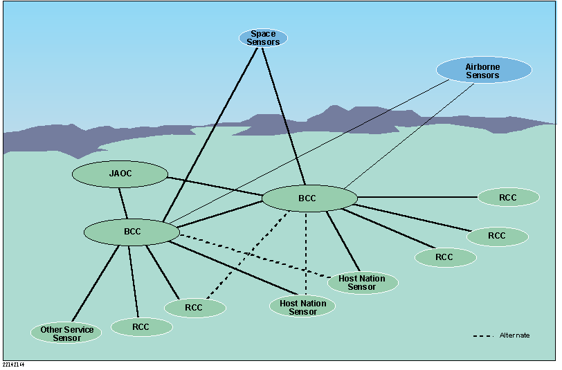
To fulfill its mission, a BCC and its supporting RCCs will deploy and/or disperse as separate elements within the assigned theater Area of Operational Responsibility (AOR). By employing as separate elements, the BCC and RCC are able to provide optimum sensor/radio coverage while ensuring mobility, redundancy, and survivability. The BCC is directly subordinate to the Joint Air Operations Center (JAOC), and is the primary USAF battle management element charged with decentralized execution of the ATO within the AOR. The BCC may be collocated with the JAOC or it may be dispersed to one or more locations within the theater. The RCC is subordinate to the BCC and provides the sensor and ground-air-ground communications capabilities that the BCC requires to perform its mission. A notional deployment of a dispersed BCC and RCCs is depicted in Figure 1.

Figure 1. Notional Deployment Configuration

1.3 References

12 December 1997

Draft System Specification for Tactical Air Operations Module, AN/TYQ-23(V)2, ELEX-T-316H/P3IC

16 December 1994

Draft Operational Requirements Document (ORD) GTACS

December 1998

Ground Theater Air Control System (GTACS) Modernization Roadmap (Draft)

9 November 1998

Air Combat Command Concept of Operations for Air Control Squadrons (Draft)

8 October 1998

Mission Need Statement (MNS) for Air Control Squadron (ACS) Command and Control (C2) Platform Modernization, ACAT Level II (Draft), CAF T3009-97

1 October 1998

R/SAOC System Requirements List, Version 2.2

11 August 1998

TBMCS System Segment Specification


1.4 System Overview

The modernized C2 Execution System for the BCC and RCC will replace the current Modular Control Equipment (MCE) and other site equipment with which the Air Control Squadrons are now equipped. Key new features that this System will provide include the following:

The modernized C2 Execution System will include the hardware, software, and communications components required to equip the BCC and RCCs. The components of the BCC will include workstations, servers, and ancillary equipment to host the theater battle management functions of the BCC and to perform operator and maintenance training. The BCC communications components will include: JTIDS terminal equipment; a suite of radios to support the TCT mission; ground-air-ground radios; and a complement of Theater Deployable Communications (TDC) equipment.

The RCC provides a self-sustaining sensor and communications capability that can be remoted from the BCC. The major components of an RCC will include the following: an organic sensor, JTIDS terminal equipment, a complement of ground-air-ground radios (remotely controlled), and a complement of TDC equipment.

There is some redundancy in the complement of equipment at the RCC and the BCC because they may be deployed independently. Long haul communications will also be collocated with the BCC and RCC. A notional system configuration for the BCC and RCC is depicted in Figure 2.

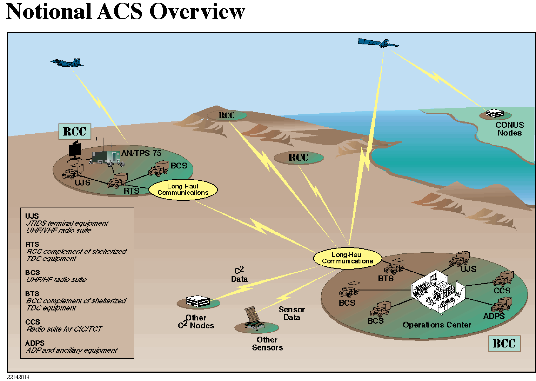
Figure 2. Notional System Configuration

This notional configuration depicts the BCC processing and communications equipment packaged in shelters transported by tactical vehicles. The operator workstations and communications access equipment may be housed using a variety of shelter options (e.g., fixed, hard, soft). The figure also depicts BCC interfaces to other C2 nodes and sensors. Figure 3 is a more complete depiction of the BCC interfaces to other systems and agencies.


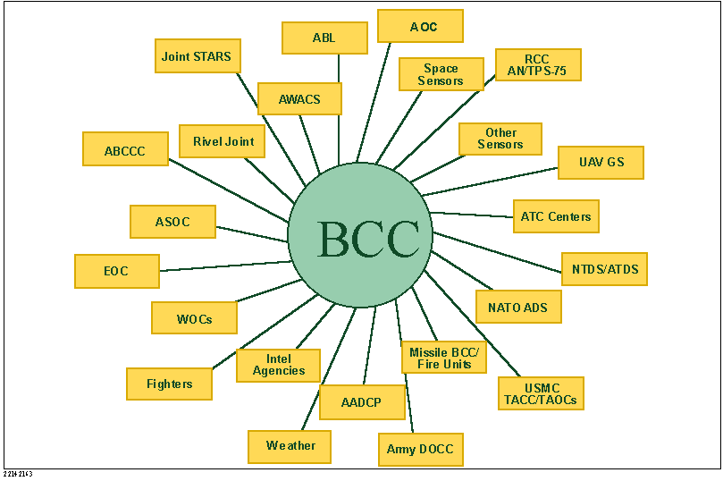
Figure 3. BCC System Interfaces to Other Systems/Agencies


1.5 Document Overview

This document contains a draft of proposed system requirements for the moderized C2 Execution System for the BCC and RCC. This draft is intended to be a vehicle to stimulate requirements discussions with the users with the aim of refining these requirements and capturing a functional requirements baseline for acquiring the system.

Table 1 provides a list of proposed system requirements in which each requirement has been numbered for identification. In the table, the functional areas and the requirements for each area appear in the order shown in the following list.:

General
Surveillance
Weapons Control
Electronic Warfare
Battle Management
Communications
Display
Training
Physical Characteristics
Environmental Characteristics
Support

The requirements have been derived from the sources identified in paragraph 1.3. Through an Operational Requirements Working Group, the system requirements list will be refined and prioritized for spiral/incremental implementation.

For the purposes of scoping the requirements in Table 1, the AN/TPS-75, the Theater Deployable Communications equipment, and the long-haul communications equipment have been handled as external interfaces. Therefore the requirements captured in this draft apply only to the BCC and RCC interfaces to these equipments.

The following definitions are provided to aid in reviewing the requirements in Table 1:

- Theater Missile Defense, Air Defense Artillery, Time-Critical Targeting
- C2 Data Link Management (to create the Single Integrated Air Picture and provide inputs to the Common Tactical Picture, and Common Operational Picture)
- Early Warning, Surveillance, Airspace Management, Intelligence
- Combat Identification
- Air Battle Execution (Offensive Counterair, Defensive Counterair, Air Refueling)

Following the system requirements list, this document contains a glossary and the following appendices:


Table 1. System Requirements for the Modernized C2 Execution System for the Battle Control Center (BCC) and Radar Communications Cell (RCC)

ID

ACS System Requirement

Priority

SR346

1 General

...

SR1

All mission application software shall be Defense Information Infrastructure Common Operating Environment (DII COE) Level 5 compliant.

E

SR2

All mission application software shall be Defense Information Infrastructure Common Operating Environment (DII COE) Level 7 compliant.

S

SR3

Components developed for the ACS shall be compliant with the Joint Technical Architecture (JTA).

E

SR4

All mission and maintenance support application software shall be Y2K-compliant.

E

SR5

Initialization of the system from a cold start using an existing database shall take no longer than 5 minutes

E

SR6

The operator shall be able to enter and change data base information without reinitialization of the system.

E

SR7

The operator shall be able to save and restore any number of alternate system initialization data bases and to create a new system initialization data base from an existing database.

E

SR8

There shall be no single point of failure that would have an impact on the continuity of the air defense operations of the system.

T

SR9

The system shall automatically reconfigure, recover, and resume operations within 5 seconds of a power or major system failure.

T

SR10

During reconfiguration or recovery, the system will continue to display initiated tracks as well as sensor plot data.

E

SR11

Security mechanisms shall be included in the system to prevent unauthorized access or tampering with the system and its processes.

E

SR12

The ACS system at a BCC shall have an interface with ACS systems at other BCCs.

E

SR13

The system shall be able to share data base information with TBMCS, other BCCs, and other C2 entities.

S

SR14

The number of BCC operator workstations shall be scalable from one to at least 100 operator positions.

E

SR15

All BCC operator workstations shall be capable of performing any operational BCC functions.

S

SR16

The system shall allow the number of operator assets for which there is more than one copy (workstations, radios, etc) to be increased or decreased without an interruption of operations.

E

SR17

The system shall be able to support printers for classified and unclassified printouts.

E

SR18

The system shall employ internally, for primary system time and position ("internal time and position"), the TBD time and position information from the Global Positioning System (GPS).

E

SR19

The system shall include synchronized voice and data recording capabilities to include playback, freeze, event filtering, switch action, and exportation for a period of 24 hours on a removable media.

E

SR20

The data recording capability shall be able to print recorded digitized primary (sensor) and secondary (beacon) plot histories, for operator selected tracks.

E

SR21

A multi-channel voice recording capability shall be provided to record each operator’s communications.

E

SR361

The system data/voice recording, playback and display capabilities shall facilitate operational mission debrief sessions including the ability to cue and present an integrated voice/data representation of any BCC operator workstation at any time selected by the operator leading the debrief session

E

SR22

The system shall include a commercial-off-the-shelf (COTS) word processor, spreadsheet, and briefing applications.

E

SR23

The system shall make maximum use of COTS and GOTS components.

E

SR24

A Single Integrated Air Picture (SIAP) shall be produced in real time (less than a 2 seconds update) from organic and non-organic sensor and data sources.

E

SR25

The Single Integrated Air Picture produced by the system shall include intelligence and other battle management data maintained by the system.

S

SR347

2 Surveillance

...

SR26

The system shall be able to perform surveillance within a minimum of 2048 x 2048 nautical mile grid for altitudes ranging from –1.3k ft. to TBDk ft. MSL

E

SR27

The system shall support the WGS-84 or the most current supportable WGS coordinate grid system for tracks and points.

E

SR28

The system shall maintain system point data for all points.

E

SR29

The system shall include a TBD (via TBMCS/AF Global Weather Service) interface to AF Worldwide Weather Service system(s).

E

SR30

The system shall automatically receive, integrate, and update weather data (e.g. winds aloft, altimeter, humidity, temperature, precipitation, forcast, and etc.) directly into system databases for all EOB/FOB locations within the theater of operations.

E

SR31

The system shall automatically receive and maintain target weather data pertinent to prosecuting TCT.

E

SR479

2.1 Sensor Control

...

SR124

The system shall provide the operator with the ability to remotely control organic sensors to include determining operational modes, implementing EW parameters, running built in tests, and return status.

E

SR125

A remote control interface shall be provided at the RCC to allow an external element to control an organic sensor.

E

SR126

The system shall provide the capability to monitor the quality of data received from organic and non-organic sensors.

S

SR127

The system shall make available to a BCC operator for evaluation all remote control and monitor data from all primary and secondary (beacon), organic and non organic (if possible/available) sensors.

E

SR128

The system shall be able to accept inputs defining the system connectivity configuration (e.g., of organic sensor, non-organic sensors, locations, sensor measurement error characteristics).

T

SR471

2.2 Sensor Input Data

...

SR32

The system shall georegister all organic and non-organic sensor plot data and IFF reports

E

SR33

All sensor and IFF reports shall be rotated automatically from the slant plane to the ground plane and parallax corrected for entry into the WGS-84 or most current supportable coordinate grid system.

T

SR34

The system shall associate IFF/SIF reports with sensor reports.

E

SR35

The system shall be able to process, integrate, and display digitized primary (sensor) and secondary (beacon modes 1, 2, 3, 3C, and 4) plot messages.

E

SR36

The system shall be able to process, integrate, and display Mode S messages.

S

SR37

The system shall accept digitized primary (sensor) and secondary (beacon) plot messages from up to three organic sensors.

T

SR38

The system shall be able to accept digitized primary (sensor) and secondary (beacon) plot messages from any sensor that outputs a CD-2 formatted plot message.

T

SR39

The system shall be able to process 3,000 plot messages per second.

T

SR40

The system shall be able to accept tactical data link track reports.

E

SR41

The system shall be able to accept time tagged sensor plot data reports from up to 30 sensors in any combination of organic or non-organic sensors.

E

SR42

The system shall be able to accept track reports from one to 30 sensors in any combination of organic or non-organic sensors.

E

SR43

The system shall process, integrate, display, and store data from Electronic Support Measures (ESM) sensors.

E

SR472

2.3 Track Initiation

...

SR44

The system shall be able to automatically initiate a track using sensor plot or IFF/SIF data.

E

SR45

The system shall be able to initiate and maintain organic and non-organic passive tracks.

E

SR46

The system shall provide the operator with the ability to enter and update non-real-time tracks.

E

SR47

The system shall provide the operator with the ability to initiate rate-aided tracks.

E

SR48

The system shall be able to automatically initiate a track from Mode S messages.

S

SR49

The system shall automatically correlate plot reports from organic and non-organic sensors over several scan periods to initiate new tracks.

E

SR50

The system shall be capable of initiating a TBM track on an object upon receipt of 4 sensor plot data reports from one organic or non-organic sensor, within a 70-second period.

E

SR51

The system shall be capable of initiating a TBM track on an object upon receipt of 3 sensor plot data reports from one organic or non-organic sensor, and 2 sensor plot data reports from other organic or non-organic sensors within a TBD period.

E

SR52

The system shall add a track to the system track database within 1 second of determining plot data is the equivalent of a new track.

T

SR53

The system shall add a track to the system track database within TBD seconds after receipt of tactical data link track data (remote track information) on a new track.

T

SR54

The tracking process shall minimize the number of false tracks and generate tracks for better than 95% of the targets in the area covered by an organic sensor.

E

SR55

Tracks that meet established criteria and that pass any filtering schemes (e.g., geographic, identity, and source filters) shall be automatically acquired as system tracks.

E

SR56

Track data shall be maintained for each system track.

E

SR57

The system shall display data on uncorrelated plot reports and non-real-time tracks as aids for the manual initiation or deletion of system tracks.

E

SR58

The system shall allow operators to convert system tracks between manual and automatic.

E

SR59

System tracks shall be initiated and maintained from the highest quality or priority data source available.

E

SR60

Controls shall be provided to allow the conversion of tracks from non-real-time to real-time, and from real-time to non-real-time.

E

SR61

The operator shall have the ability to designate any non-real-time track as requiring special processing with regard to security filters.

E

SR62

The system shall drop uncorrelated reports and newly initiated tracks that lie within user defined geographic areas.

E

SR63

Remote tracks that lie within user defined geographic areas shall be dropped.

E

SR64

The system shall discard all organic and non-organic sensor/IFF track and/or plot reports within a user-defined sensor area associated with a specified primary or secondary (beacon) sensor.

E

SR65

The system shall support up to 20 sensor areas for a primary or secondary sensor.

E

SR66

Tracks entering a sensor area shall be dropped unless they are changed to rate aided tracks.

E

SR67

The system shall be able to process tracks received from other BCCs or external sources that provide tracks in a format supported by the system.

T

SR473

2.4 Correlation

...

SR68

Multi-sensor correlation shall be performed on local and remote tracks.

E

SR69

The system shall be able to correlate track data from one to 30 sensors in any combination of organic or non-organic sensors.

E

SR70

The system shall correlate data link inputs with existing system tracks and convert new remote tracks into system tracks.

E

SR71

The system shall determine if a local track correlates with any other local or remote track within 1 second of establishing or updating that local track.

E

SR72

The system shall determine if a remote track correlates with any of it’s local tracks within 1 second of establishing or updating that remote track.

E

SR73

Target position, IFF codes, track numbers, source identification, and link quality shall be used automatically in a manner that supports correlation.

E

SR74

Uncorrelated plot reports shall be displayed

E

SR474

2.5 Track Updating

...

SR75

The system shall update a track within TBD seconds after receipt of sensor plot data (from an organic or non-organic sensor) on an object for which the system has already established that track.

E

SR76

The system shall update a track in the system track database within TBD seconds after receipt of sensor track update data (track data from an organic or non-organic sensor that is identified as corresponding to a track already known to the system).

T

SR77

The system shall update a track in the system track database within TBD seconds after receipt of tactical data link track update data (remote track information that is identified as corresponding to a track already known to the system).

T

SR78

The system shall automatically correlate organic and non-organic sensor plot reports for each scan with newly established (tentative) tracks and with established tracks to smooth tracks and to predict target position and velocity.

E

SR79

The estimated current location of all targets represented by real-time system tracks shall be recomputed at intervals based on the track update cycle.

E

SR80

System tracks maintained through sensor track messages shall be updated at a rate sufficient to ensure their integrity.

E

SR475

2.6 Other Track Processing

...

SR81

An operator shall have the ability to manually establish, delete, or filter system tracks and points.

E

SR82

The system shall calculate, display, and employ in data link operations a Track Quality/Position Quality metric, as defined by MIL-STD-6016, for every local track/point.

E

SR83

The system shall display and employ in data link operations the Track Quality/Position Quality metric, as defined by MIL-STD-6016, for every remote track/point.

E

SR84

The system shall be able to process at least 5000 system tracks (i.e., tracks from organic and non-organic sensors, and tracks from tactical data link sources, in any combination).

E

SR85

A system track, either real-time or non-real-time, and rate-aided tracks, shall be designated as lost when data is insufficient to maintain the track according to user defined parameters.

E

SR86

The system shall drop a local lost track for which there hasn't been an update from a local radar, a shift in reporting responsibility to another data link Interface Unit, or an operator initiated manual update within 40 seconds.

E

SR87

The system shall purge from its database/display a remote track that has not been updated within a sufficient time period.

E

SR88

The system, using sensor plot data from organic and non-organic sensors, shall be able to detect, identify, classify, and predict launch and impact points, and estimated heading for all Theater Ballistic missiles (TBMs) with RCS greater than (TBD pending further research, particularly with the Threat Assessment) size in the access sensor volume.

E

SR89

The system shall be able to group from 1 to 25 tracks into a raid to reduce display loading, datalink reporting, and the operator workload.

E

SR476

2.7 IFF/SIF Modes and Codes

...

SR90

The operator shall have the ability to initiate IFF Mode 1, 2, 3, 4, and C interrogation of any track.

E

SR91

The system shall be able to interrogate mode 4 tracks in accordance with user specified time, identification, and location parameters.

E

SR92

The Mode 4 response from the sensor shall include the confidence level for the response as follows: NO DECISION, NEGATIVE, LOW CONFIDENCE FRIEND, HIGH CONFIDENCE FRIEND.

T

SR93

The data for a track shall include any IFF Mode 1, 2, 3, 4, or C (altitude) responses received from a sensor.

E

SR94

The data for a track shall include any Mode S responses.

S

SR95

The operator shall have the ability to initiate Mode S interrogation of any track.

S

SR477

2.8 Track Identification

...

SR96

The system shall provide for automatic and manual identification of tracks.

E

SR97

The identification categories shall be (1) PENDING, (2) UNKNOWN, (3) ASSUMED FRIEND, (4) FRIEND, (5) NEUTRAL, (6) SUSPECT, and (7) HOSTILE.

E

SR98

Operator action shall be required for all tracks identified as HOSTILE.

E

SR99

The initial identity of a track shall be PENDING unless the track is otherwise identified when initiated.

E

SR100

The system shall preclude the operator from changing the identity of a track from any identification category back to PENDING.

E

SR101

The system shall identify tracks automatically according to user defined identification decision tables.

E

SR102

The system shall be able to associate specific aircraft/mission categories with any of the 31 valid Mode 1 IFF codes.

E

SR103

The system shall be able to associate the IFF Mode 2 or 3 responses for an aircraft track with Mode 2 or 3 codes for specific aircraft contained in an Air Tasking Order (ATO).

E

SR104

The system shall support the use of NATO Mode 3 codes and Code Validity Intervals (CVIs).

E

SR105

The system shall use operator selectable identification modes to control the identification process.

E

SR106

The system shall be able to prioritize tracks based on user defined threat inputs.

E

SR107

The system shall have the ability to identify tracks based on flight plan correlation.

E

SR108

The system shall be able to receive and process flight plans in the FAA and ICAO formats.

E

SR109

The system shall have a capability to store 20,000 flight plans in any 24-hour period.

E

SR110

The system shall have capability to process 10,000 simultaneous flight plans.

E

SR478

2.9 Track Classification

...

SR111

The system shall maintain classification data on all system tracks to provide further categorization of tracks by mission and weapons type.

E

SR112

Automatic classifications shall be performed on the basis of information in ATOs, data link messages, IFF codes, and manually entered data.

E

SR113

Friendly tracks that are self-reported through TADIL-J PPLI messages shall be automatically classified with the data contained in those messages.

E

SR114

Other friendly tracks shall be semi-automatically classified by correlation with IFF data and flight data made available from ATO and other aircraft control agencies.

E

SR115

Available IFF Mode 1 and Mode 3 codes for a track shall be matched to Mode 1 and Mode 3 codes for stored classification data.

E

SR116

The Mode 2 code for a track shall be matched against ATO codes for stored classification data. If a match is found, the ATO mission and aircraft type shall be assigned to the track.

E

SR117

Automatically assigned classification data shall be displayed for the operator, who may change the classification data or the data which permitted the classification to be made automatically.

E

SR118

In the event of classification conflict, the operator shall have the ability to manually override automatically assigned classifications.

E

SR119

The system shall be able to associate the IFF Mode 3 response for an aircraft track with any of up to 16 valid special purpose Mode 3 codes.

E

SR120

The system shall provide a unique alert message for any of a total of ten additional special IFF codes, in any mode.

E

SR121

The system shall require operator confirmation when changing an air track to a surface track or a surface track to an air track.

E

SR122

The system shall provide the operator with the information needed to identify and resolve identification and classification conflicts, track number conflicts, and anomalies in correlation and tracking.

E

SR123

The system shall convert track identification and classification data between local and remote tracks in accordance with the appropriate MIL-STDs (e.g, 6016, 6011).

E

SR480

2.10 Distribution of Results

...

SR129

System tracks (including data link tracks) and points shall be eligible for transmission over data links.

E

SR130

The system shall be capable of assuming reporting responsibility for local track data, and of transmitting track data to the tactical data network in accordance with reporting responsibility rules.

E

SR131

A real-time computed track report (position heading, velocity, and altitude) or a PPLI (position, velocity, altitude, self-identification status) shall be used for intercept calculations and data link reporting.

E

SR132

The system shall support an automatic and a manual track number assignment scheme in accordance with data link standards for track accountability so that system tracks can be accessed for necessary functions and data link operations can be performed under applicable protocol rules.

E

SR133

The system shall participate in the Joint Composite Tracking Network through interfaces that are TBD.

S

SR348

3 Weapons Control

...

SR134

The system shall support the designation of weapons systems (aircraft or SAM) and targets for automated weapon-target trials.

E

SR135

The system shall allow for operator assignment of a designated weapon system to any designated target, track, or point.

E

SR136

The assignment of a target to a designated weapon system shall not result in the override of the previous assignment.

E

SR137

The system shall allow the operator to prioritize engagements for weapon systems.

E

SR138

As a result of pairing, the system shall automatically compute an intercept solution.

E

SR139

The system shall be able to calculate hundreds of simultaneous intercepts for all the weapons systems within the BCC AOR.

E

SR154

Winds aloft data received by the system shall be considered in all intercept calculations.

E

SR140

The computed solution shall be updated when parameters are changed either by operator input or by movement of the weapon system and/or target.

E

SR167

An operator shall be able to override any automatic weapons control capability.

E

SR511

3.1 Aircraft Weapons Control

...

SR141

The system shall be able to generate all necessary orders and aircraft guidance messages for use by the operator during voice controlled intercepts and for transmission via TADIL-C and/or TADIL-J during data link controlled intercepts

E

SR142

The system shall check for and alert the operator to the presence of conditions that would make an intercept infeasible.

E

SR143

The system shall monitor intercept parameters and make the operator aware of parameter values and changes affecting the intercept.

E

SR144

The system shall provide the capability to calculate a Cutoff intercept type.

E

SR145

The system shall provide the capability to calculate a Stern intercept type.

E

SR146

The system shall provide the capability to calculate a Pursuit intercept type.

E

SR147

The system shall provide the capability to calculate a Point Parallel Air Refueling intercept type where the operator is capable of specifying the slant and offset ranges employed.

E

SR148

The system shall be able to calculate each intercept type for airborne interceptors or ground strip alert aircraft.

E

SR149

Angles of bank in all intercept calculations shall be determined by aircraft performance and interceptor speed for interceptors, or by operator entry/default value for tankers.

E

SR150

The system shall have the capacity to store interceptor data sets that contain clean and tanked aircraft performance data from all available military aircraft, shall be capable of associating with the ATO to employ the appropriate interceptor data set for intercept solution calculations, and shall have sufficient spare capacity to allow interceptor data sets to be updated and/or expanded to incorporate future aircraft types.

E

SR151

The maximum rate of turn in any intercept calculations shall be in accordance with the appropriate aircraft manual.

E

SR152

The altitude and speed parameters used for all intercept computations shall be based upon profile, threat types, altitudes, weapons launch, and performance envelope considerations.

E

SR153

Magnetic variation shall be considered in all intercept calculations.

E

SR155

In any mode of automation and in the absence of an operator selected intercept type, the system shall use a default intercept type for the calculation of intercept solutions.

E

SR156

The system shall provide intercept speed profiles for intercept solution calculations.

E

SR157

In any mode of automation and in the absence of an operator defined speed profile, the system shall use a default speed profile for the calculation of intercept solutions.

E

SR158

During the calculation of an intercept solution, the system shall determine the intercept command attack altitude.

E

SR159

In any mode of automation, the system shall provide operators with the capability to modify command altitude and speed parameters used for the calculation of intercept solutions.

E

SR512

3.2 SAM Control

...

SR160

Weapon assignment for a SAM shall be only to tracks with non-friendly identities or to tracks with friendly identities that have a hostile-exercise indicator set.

E

SR161

The system shall have the capacity store and employ SAM performance data sets for all available types of friendly/enemy surface to air missiles (SAMs), and shall have space capacity sufficient to allow SAM performance data sets to be updated and/or expanded to incorporate future SAM types.

E

SR162

The system shall permit the operator to control all displays, intercept/trial calculations, orders, and messages relating to Surface-to-Air Missile (SAM) control.

E

SR163

The system shall support simultaneous command and control of multiple SAM entities as supported by data link connectivity.

E

SR164

The system shall be able to generate and transmit orders to SAM entities.

E

SR165

The system shall be able to receive, process, and display messages (including data link messages) from SAM entities.

E

SR166

Upon operator selection, the system shall automatically process and display interceptor and SAM entity engagement status/results based upon received data link messages and/or received voice reports that have been manually entered in to the system.

E

SR513

3.3 Airspace Management

...

SR169

The system shall be able to direct, route, assist, monitor, and maintain safe positive control of friendly or cooperating aircraft in the AOR.

E

SR168

The system shall alert the weapons control operator when friendly aircraft, not within a safety corridor, penetrates a Missile Engagement Zone (MEZ).

E

SR170

The system shall be able to generate and display command data to support voice or data link airspace management operations..

E

SR171

The system shall provide the capability to permit the operator to assign simultaneously a minimum of 20 friendly aircraft-to-aircraft join-ups regardless of aircraft types.

E

SR172

The system shall provide the operator with the capability to initiate transfer of control orders (via voice or TADIL data link), to effect handovers between agencies (via voice or TADIL data link), and to request handovers (via voice or TADIL data link) from ATC (ICAO, FAA, and military ATC) and other command and control agencies.

E

SR173

The system shall provide the operator with the capability to initiate automatic transfer of control orders, to effect automatic handovers between agencies, and to request automatic handovers from ATC (ICAO, FAA, and military ATC) and other command and control agencies.

S

SR174

The system shall provide automatic minimum safe altitude and separation notification for fighter and other designated aircraft, in both the vertical and horizontal planes, and give both visual and aural alarms for out-of-tolerance conditions.

E

SR349

4 Electronic Warfare

...

SR175

The system shall have the capability to receive, process, and selectively display sensor/IFF jam strobes for organic sensors and non organic sensors if available.

E

SR176

The system, using tactical data links, shall be able to transmit, receive, and forward jam strobes and amplifying information as EW tracks IAW applicable data link standards.

E

SR177

The system shall provide the capability for the operator to determine the location of a sensor jammer.

E

SR178

The capability shall be provided to initiate and transmit alerts to sensor sites for the purpose of initiating Electronic Protection (EP) measures.

E

SR179

Operators shall be provided the capability to control, according to operator determined schema, the emission of each organic sensor (and non organic when feasible) and IFF separately and independently including, but not limited to, blinking, Pulse Repitition Frequency (PRF)/frequency agility, and transmission algorithms, blanking, use of decoys, and/or deactivation of radiating equipment.

E

SR180

The system shall be able to generate, process, and display anti-radiation missile (ARM) alerts and messages.

E

SR181

The system shall incorporate the capabilities to counter jamming interference through the use of jam resistant radios and associated devices and techniques.

E

SR350

5 Battle Management

...

SR182

The system shall be able to receive, store, and automatically update databases with current information from the Air Tasking Order (ATO) and Airspace Control Order (ACO) for use in correlation, identification, classification, and operator displays.

E

SR183

The system shall be able to automatically store the Space Tasking Order (STO) for use in aerospace management tasks within the assigned area of responsibility.

S

SR184

The system shall provide a near-real-time graphical display of theater air, ground, and sea tracks, all-source correlated information about enemy forces, and other battle management information.

E

SR185

The system shall include decision aids to support identification of time critical targets (TCTs), to monitor the movement of TCTs, and to direct weapons against TCTs.

E

SR186

The system shall include decision aids to aid in nomination of TCTs, selection of weapons to engage TCTs, coordination of tasking, and dissemination of tasking to C2 agencies.

E

SR187

The system shall maintain force status data pertinent to prosecuting TCTs including, as a minimum, status of weapons systems, friendly airfields, C2 systems, and surveillance systems.

E

SR188

The system shall be capable of receiving, processing, and displaying MTI/SAR data from JSTARS.

E

SR189

The system shall provide a capability to generate ground tracks based on MTI data received from JSTARS.

E

SR190

The system shall provide a capability to coordinate ground target nominations.

E

SR191

The system shall provide a capability to transmit radar service requests (RSRs) to JSTARS.

E

SR192

The system shall provide a capability to record and playback MTI data.

E

SR193

The system shall provide the capability to store data for playback for 168 hours.

E

SR194

The system shall be capable of receiving, processing, and displaying video and telemetry data from a UAV ground station.

E

SR195

The system shall be capable of receiving, processing, and displaying video, telemetry, and other processed data from multiple UAV ground stations.

S

SR196

The system shall provide a capability to predict mobile threat movement or location suitability by means of area limitation.

E

SR197

The system shall provide Automated Application Intelligence Preparation Battlespace (A2IPB) products and tools to refine TCT identity and location estimates.

E

SR198

The system shall fuse/correlate missile data from multiple sources to improve situation awareness and ensure that TCT operators have the best possible information to conduct TCT missions.

S

SR199

The TCT capabilities of the system shall include support to Theater Missile Defense (TMD) active defense operations.

S

SR200

The system shall disseminate warnings of theater missile events to C2 agencies by means of voice and data link.

E

SR201

The system shall display airborne theater missile threats, identify systems that could engage threats, and disseminate missile cueing data.

S

SR202

The system shall provide a capability to display and deconflict airspace information to support the execution of the Air Battle Plan.

E

SR203

The system shall provide a capability to create, edit, and maintain Requests for Information (RFI) from organic, theater, and national sensor sources and to transmit these requests to the AOC or other external agencies.

S

SR204

The system shall include a capability to display national and tactical sensor coverage.

E

SR205

The system shall provide the functionality to monitor and track execution of the Air Battle Plan or Air Battle Tasking released for operations, and to provide status updates (e.g., actual takeoff times) to support mission replanning.

E

SR206

The system shall provide a capability to create and disseminate scramble tasking orders for air defense, joint strike, reconnaissance, and other missions for aircraft which are placed on alert.

E

SR207

The system shall provide the capability to display tabular and graphical views of mission schedule and status information, and to monitor, track, and update mission execution by means of these tabular and graphical views.

E

SR208

The system shall be capable of processing and displaying track data, C2 data, and intelligence data from service and national intelligence agencies received over the following satellite broadcast nets: TIBS, TDDS, TOPS/TADIXS-B, OTCIXS.

E

SR209

The system shall provide a capability to retrieve, and access, intelligence information as defined by the DIA MIDB to include Orders-of-Battle, NRT track data, and ATO information in support of mission execution.

E

SR210

The system shall provide a capability to monitor and project resource availability necessary for mission execution including but not limited to battle management of critical resources such as: aircraft, airfields, and munitions.

E

SR211

The system shall provide a capability to monitor and display events and information that designate potential threats and targets.

E

SR212

The system shall provide a capability to access and display target lists including Candidate Target Lists and Target Nomination Lists.

E

SR213

The system shall provide a capability to access and retrieve imagery and image products from on-line and off-line storage.

E

SR214

The system shall provide a capability to transmit imagery data to shooters.

S

SR215

The system shall be capable of running GCCS applications.

E

SR216

The system shall be capable of transmitting/receiving USMTF message traffic to support Battle Management, reporting to higher headquarters, and other operations.

E

SR351

6 Communications

...

SR362

The system shall be capable of establishing and maintaining interfaces with external and internal agencies and services for the purpose of exchanging data and voice information. Agencies and services not included within the system and with which the system must interoperate are defined as external; agencies and services within the system and which must be provided in order for the system to accomplish its assigned missions are defined as internal.

E

SR403

The system shall provide the capability to assign each internal and external interface an unrestricted or minimally restricted subset of system assets through software configuration and reconfiguration.

E

SR443

The system shall be capable of being reconfigured while in operation and such reconfiguration shall affect only those elements being reconfigured.

T

SR444

For all subsets of assets assigned, the system shall provide each position with a means for ready access, use, and control of the assigned asset(s).

T

SR433

6.1 Interfaces with External Agencies and Services

...

SR363

The system shall be capable of interfacing with each of the agencies and services listed in Appendix Table A.1, External Agencies and Links.

E

SR397

The system shall maintain interfaces with the agencies and services listed in Appendix Table A.1 using off-the-shelf interfacing equipment consisting of modems, data terminal sets, radios, and other LAN/WAN communications systems as appropriate. As available, interfacing equipment shall include the features of: software/firmware reconfigurability; remote control and status monitoring; and operate such that failure or removal of any device does not affect operation of any other.

E

SR436

6.1.1 Data Interfaces with External Agencies and Services

...

SR364

At the discretion of the user during initialization, the system shall be capable of effecting an interface with an external agency or service using any of the data links listed in Appendix Table A.1.

E

SR368

The system shall accommodate the incorporation of future data links with minimal impact to the hardware, firmware, and software associated with the implementation of existing operational links.

O

SR445

The system shall provide operators with the capability to associate with each link a circuit identification number and to establish each data link for forwarding or non-forwarding operations.

T

SR365

Link protocols, message standards, and implementation of the external interfaces shall be in accordance with the appropriate documents listed in Appendix Table A.2.

E

SR366

The system shall have the capability, in accordance with MIL-STDs, to generate, format, deformat, transmit, receive, filter, retransmit, forward, and use as appropriate, including display, the tactical data link messages listed in Appendix Table A.3.

E

SR367

The system shall provide the operators the capability to forward or retransmit messages, as appropriate, between any TADIL-A, TADIL-B, TADIL-J, SADL, ATDL-1, or NATO Link-1 interface.

E

SR447

Operators shall be provided the capability to specifically identify the data link from which and the data link(s) to which forwarding/retransmission shall be inhibited.

T

SR369

Operators shall be provided the capability to establish forwarding filters for each data link selected for forwarding.

E

SR524

Forwarding filters shall filter messages according to operator defined environment/category parameters

T

SR431

The system shall be capable of displaying transmitted and received data link messages at each operator console.

E

SR448

Processed data link message information shall be displayed in track/point symbology, tabular display information, and operator interfaces.

T

SR450

At a minimum in support of data link operations, the system shall provide operators the capabilities: to monitor all data links by link type, by message type, and by track; to monitor data link messages transmitted and/or received at the message level; and to pause on a selected transmitted or received message and view the parsed contents of the message.

T

SR430

The system shall be capable of receiving and displaying the USMTF Operations Tasking Data Link (OPTASKLINK) and Tactical Operations Data (TACOPDAT) messages and using the information to initialize the system data links.

E

SR432

The system shall be capable of filtering data transmitted/received on each TADIL-A, B, J, ATDL-1, NATO Link 1, or SADL data link using the criteria specified for each data link in Appendix A-4.

E

SR371

The system shall support the capability to relay data between all data links where standards allow.

E

SR370

The system shall be capable of: supporting up to 5 TADIL-A networks.

E

SR372

The system shall be capable of supporting, in any combination, a minimum of 35 TADIL-B and ATDL-1 tactical data links.

E

SR373

The system shall be capable of supporting a minimum of TBD NATO Link 1 tactical data links.

E

SR374

The system shall be capable of supporting a minimum of 10 full-duplex TADIL-C links.

E

SR375

The system shall be capable of supporting a minimum of TBD Situational Awareness Data Links (SADL).

E

SR376

The system shall be capable of supporting a minimum of 5 Link 16 networks.

E

SR377

The system shall be capable of supporting 35 Serial J data links.

E

SR378

The system shall be capable of supporting a Socket J.

E

SR379

The system shall be capable of interoperation with the Defense Message System.

E

SR380

The system shall be capable of supporting TBD Joint STARS interface(s) for the purpose of receiving MTI and SAR data and for transmitting radar service requests in accordance with TBD.

E

SR381

The system shall be capable of serving as a Joint STARS ground station for the purpose of receiving MTI and SAR data and for transmitting radar service requests in accordance with current ground station capabilities.

O

SR382

The system shall be capable of receipt, display, and distribution of UAV video and telemetry products in accordance with TBD.

E

SR383

The system shall be capable of receiving and processing intelligence and tactical data received from external TIBS, TOPS, TDDS, TADIXS-B, and OTCIXS networks or follow-on services in accordance with TBD.

E

SR384

The system shall be capable of: receiving GBS broadcasts; storing selected portions of the received broadcasts; and forwarding selected products within the system.

E

SR385

The system shall be capable of performing GBS inserts.

O

SR386

The system shall support data exchange with, at a minimum, weather agencies, USAF and other services, and civilian agencies using TCP/IP and ATM protocols and employing SIPRNET, NIPRNET, and internet.

E

SR387

The system shall be capable of: receiving; supporting operator selection of; and directly employing time and position data, as available, from GPS, JTIDS networks, and tactical timing sources.

E

SR388

The system shall be capable of interfacing with US and foreign Air Traffic Control (ATC) Centers for the purpose of receiving automated flight plan data and performing aircraft handovers.

E

SR389

The system shall be capable of exchanging red-to-red and/or black-to-black data base information with US and foreign (as available) Air Traffic Control Centers for the purpose of receiving automated flight plan data and performing aircraft handovers.

O

SR390

The system shall support common SIPRNET and NIPRNET services including email, file transfer, and soft office functionality.

E

SR391

The system shall support secure and non-secure video teleconferencing with other selected hosts.

E

SR392

The system shall support secure and non-secure facsimile as a network accessible device.

E

SR393

The system shall support interface with all standard Air Force personnel, administrative and logistics management systems.

E

SR394

The system shall provide the operator the capability to receive, process and transmit EAMs.

E

SR395

The system shall be capable of interfacing with the NORAD and FAA sensor systems for the purpose of accessing, displaying, and utilizing sensor data.

O

SR525

The system shall be capable of interfacing, controlling, and employing NORAD communications assets.

T

SR396

The system shall be capable of employing IDM interfaces.

E

SR437

6.1.2 Voice Interfaces with External Agencies and Services

...

SR398

The system shall provide operators the capability to establish and maintain secure and nonsecure voice connectivity with those external agencies and services in Appendix A.1 which support voice connectivity using: organic radio, JTIDS voice, commercial telephone, tactical telephone, Theater Deployable Communications equipment, or interfaced long haul tactical communications equipment. The use of other system features such as, but not limited to, conferencing or net radio operation may be controlled but not precluded by virtue of operation with an external agency or service.

E

SR439

6.1.3 External Equipment Interfaces

...

SR399

The system shall support interfaces with external tactical and commercial communications equipment, organic sensors, and non-organic sensors including, at a minimum, equipment listed in Appendix A.5 and in accordance with the associated equipment ICDs listed in Appendix A.5.

E

SR434

6.2 Connectivity Between Internal Elements

...

SR400

The system shall be capable of establishing and maintaining secure and non-secure voice and data connectivity, as appropriate, between the internal system and, in like manner, at the RCC and between BCC and RCC.

E

SR440

6.2.1 Data Connectivity Between Internal Elements

...

SR401

Data connectivity between internal elements shall employ redundant local area network (LAN) technology capable, by employment and by inherent capacity, of supporting a threefold growth in system size.

E

SR451

LAN technology shall provide the capabilities to support data sharing and data base maintenance.

T

SR452

LAN implementation shall utilize COTS equipment to the maximum extent possible.

T

SR453

LAN technology, equipment, naming conventions, and protocols employed in the system shall be compatible with those employed by the AOC.

T

SR454

LAN technology and equipment employed in the system shall be capable of being operated with equipment at both the BCC and RCCs.

T

SR455

LAN equipment shall be interoperable with TDC equipment.

T

SR456

Systems administration of data LANs at the RCC shall be capable of being remotely managed by BCC system administrators.

T

SR402

Data LAN equipment interconnecting internal elements shall be readily scalable and configurable to accommodate all addressable connected elements.

E

SR441

6.2.2 Voice Connectivity Between Internal Elements

...

SR404

Redundant LAN technology, separate from that supporting data operation and employing COTS equipment, shall be used to support interconnection of system voice users and equipment.

E

SR457

The capability shall be provided to utilize voice communications equipment in the absence of data system operation.

T

SR405

Voice LAN equipment interconnecting voice users and equipment shall be readily scalable and reconfigurable to accommodate all connected users and equipment items.

E

SR458

Systems administration of voice LANs at the RCC shall be capable of being remotely managed by BCC system administrators.

T

SR406

Voice LAN technology shall be capable, by employment and by inherent capacity, of supporting a threefold growth in system size.

E

SR407

For each voice connection supported, the system shall provide individually or in combination, as appropriate, the capabilities to select the following modes of operation: Plaintext/Ciphertext (PT/CT); talk (receive/transmit); off (no reception or transmit); call (dialing/addressing); and eavesdrop-monitor. As appropriate, each system-supported voice connection shall employ "hot mike" and push-to-talk ("keyed" by switch/foot-switch action) operation.

E

SR408

A non-blocking intercommunications system (intercom) shall be provided for all positions, including operators, maintenance positions, and positions assigned to radars. The intercom capability shall include, but not be limited to, the capabilities to support: keyed operation; multiple, user-defined networks of positions; console to console communications; and, a monitor mode.

E

SR409

The system shall support operator-designated destinations for audible alerts and voice communications. Destinations shall include, but not be limited to, one or more headsets and one or more speakers. A priority scheme shall be provided allowing the volume of audible alerts to be operator-specified.

E

SR459

Visible alerts shall be provided and the operator shall be provided with the means of selecting either audible, visible or both forms.

T

SR410

Each operator shall be provided the capability to transmit, receive, monitor, and control all system radios in secure and nonsecure modes. For JTIDS operation, the same capabilities shall be provided for secure operation only.

E

SR411

The system shall provide the capability to establish secure and non-secure multi-user radio nets using all assigned radios, of any type, which are keyed simultaneously. JTIDS voice participation in multi-user radio nets is limited to secure nets.

E

SR412

The system shall provide volume control for the system voice radio circuits and intercom circuits enabling the operator to adjust volume levels on an individual circuit basis.

E

SR413

Each operator shall be provided access to the tactical (two and four wire), commercial, tactical-secure, DSN and commercial-secure telephone service(s) via either tactical switching equipment or TDC equipment or both.

E

SR460

The system shall include, for telephone access, a dialing capability and associated signaling and supervision.

T

SR461

The system shall support point-to-point circuits with operator-initiated ringdown and the use of "hot lines" enabling automatic initiation of a ringdown at the distant end upon "going offhook."

T

SR462

The system shall support the use of secure and non-secure telephone instruments including POTS and STU-IIIs, or equivalents.

T

SR415

Radio equipment incorporated into the system shall include the capability to receive and transmit on all guard frequencies and have the selectable option of monitoring and/or transmitting on guard frequencies while operating on other assigned frequencies. The system voice distribution capability shall support unblocked distribution of guard channel voice reception and transmission.

E

SR442

6.2.3 Internal Equipment Interfaces

...

SR416

The system shall support interfaces with internal communications equipment including radios, modems, and data terminal sets in accordance with the ICDs and quantities listed in Appendix A.6.

E

SR417

Full control of all assigned ground-air-ground radio communications shall be provided to include remote control of operational modes, status monitoring, and initiation of BIT.

E

SR463

The system shall be capable of supporting local and remote JTIDS terminal operation for terminals sited at the BCC, the RCCs, or both.

T

SR418

The system shall be capable of hosting a minimum of 5 primary MCE Class 2 JTIDS Terminals.

E

SR419

JTIDS Terminal integration shall be capable of supporting a hot-standby terminal for each primary terminal.

E

SR464

The system shall support primary/hot-standby terminal interoperation to: permit the hot-standby terminal to maintain synchronization with the primary and to monitor the primary terminal’s Link 16 network; permit automatic switchover from primary to hot-standby in the event the primary terminal cannot be utilized; and permit manual switchover at operator discretion.

T

SR420

Messages sent to a JTIDS terminal shall be metered using a method that minimizes data latency, accounts for transmit opportunities associated with the terminal's Network Design Load (NDL) and prevents the overflow of terminal's transmit buffers.

E

SR421

System JTIDS terminals operating within the same Link-16 network shall be capable of simultaneously broadcasting the same TADIL J messages.

E

SR422

When any of the system JTIDS terminals are operating in separate Link-16 networks, the system shall be capable of forwarding messages between the networks.

E

SR423

The system shall be capable of supporting JTIDS Time Slot Reallocation.

E

SR424

The system shall support the dynamic management of Link 16 slot block assignments via manually entered updates and via Link-16 messages transmitted/received in accordance with the rules specified in MIL-STD-6016

O

SR425

A JTIDS Terminal communications, control, and status monitoring capability shall be provided to support primary and hot standby terminals in the system.

E

SR526

To the extent available, the system shall incorporate products from the USAF Link 16 Low Cost Integration (LCI) effort.

T

SR527

At a minimum, the system shall incorporate primary/hot-standby terminal discrete signals for: the Notch Filter Assembly; the terminal On/Off/Standby; the Built-In-Test (BIT) fail identification; and the JTIDS voice.

T

SR528

The system shall provide, for each JTIDS terminal, a capability to utilize the terminal’s External Time Reference interface to provide GPS time to the terminal.

T

SR529

The system shall provide the capability to download a terminal’s Network Interface Computer Program (NICP) and/or Subscriber Interface Control Program (SICP) into the terminal via the terminal’s Support Port interface.

T

SR426

The system shall be capable of initializing each JTIDS Terminal (both primary and hot-standby) using an operator selected Network Design Load (NDL).

E

SR530

The system shall support terminal initialization by providing the capability to process, store, and employ NDLs received electronically or via floppy disk.

T

SR531

The system shall support terminal initialization by providing the capability to parse and display any operator-selected NDL.

T

SR532

The system shall support terminal initialization by providing the capability to break out individual field values associated with initialization data block words.

T

SR533

The system shall support terminal initialization by providing BCC operators with the capability to edit any data block word field of a selected NDL.

T

SR427

The system or operator shall be capable of initiating Line Replaceable Unit (LRU) and Shop Replaceable Unit (SRU) BIT for each JTIDS Terminal (both primary and hot-standby).

E

SR428

The system shall be capable of processing, displaying, and printing the terminal (both primary and hot-standby) status monitoring and diagnostic information.

E

SR435

6.3 Communications Security

...

SR429

The system shall support encryption of external communications interfaces and, as required, internal communications interfaces all to the level of SECRET.

E

SR414

The system shall be capable of actively constraining participation in external communications networks to those sources which are either all plaintext or all ciphertext but not mixed.

E

SR466

Attempts to operate voice or data circuits in a manner which would result in a security violation or which violate standard USAF regulations and procedures shall result in an alarm or warning.

T

SR352

7 Display

...

SR217

The system shall support a minimum of 2048 x 2048 nautical mile grid for altitudes ranging from –1.3k ft. to TBDk ft. MSL

E

SR218

The operator shall be able to select display range scales of 25, 50, 100, 200, and 500 miles as measured from the display center to the nearest edge.

T

SR222

The system shall provide the capability to offset the display and to center a display that has been offset.

E

SR223

The system shall display weapons control conditions, air defense alert conditions, weapon control mode, and the threat mode.

E

SR224

The system shall display the time in hours, minutes, and seconds in multiple operator selectable time zones.

E

SR229

The system shall display the data associated with operator selected objects.

E

SR230

The operator shall have the ability to select data blocks for display adjacent to the symbols for selected tracks, points, and other objects.

E

SR233

The system shall allow the operator to resize individual display windows.

E

SR234

The system shall provide for customized drop-down menu with operator defined switch actions.

E

SR242

The system shall provide a tabular display of any data contain in the system database.

E

SR270

The system shall be capable of displaying weather information.

E

SR272

The system shall provide positive feedback of acceptance of any manually entered parameters, track locations, changes in track file elements or other operator data/instructions in no more than one second.

E

SR273

The system shall provide separate intensity/accentuation controls for selected display objects.

E

SR274

All pertinent commands, orders, messages, and operations relating to a function shall be available on operator demand.

E

SR481

7.1 Maps and Overlays

...

SR219

The system shall be capable of displaying worldwide NIMA map data.

E

SR220

The system shall provide the operator the capability to enter maps and overlays for display.

E

SR221

Maps and overlays shall be selectable by the operator.

E

SR254

The operator shall control the system’s display of specified geographical areas.

E

SR482

7.2 Plots and Tracks

...

SR225

The system shall be able to display the digitized primary (sensor) and secondary (beacon) plot data from the most recent sensor sweep of any of the organic sensors.

T

SR226

The system shall be able to display a history of digitized primary (sensor) and secondary (beacon) data by displaying the plot data from the 6 previous sensor sweeps of any of the organic sensors.

T

SR227

The system shall be capable of displaying Track/Point symbology and data.

E

SR228

JU tracks shall be identified by a unique symbol or symbol modifier.

E

SR231

Operators shall be able to select velocity vectors for display with each track.

E

SR232

The system shall provide the operator the capability to designate tracks for special display (color, size, bold, intensity of individual tracks).

E

SR235

An operator shall be able to display the IFF numeric codes for a selected track.

E

SR236

An operator shall be able to display sensor plot reports, IFF returns , and declared target strobes for any one of the organic and non-organic sensors.

E

SR237

The system shall have the ability to display tracks with specified IFF modes and codes.

E

SR238

The system shall color code IFF returns up to 10 colors.

E

SR239

An operator shall be able to select tracks for display on the basis of any IFF/SIF mode or code or combination of modes and codes.

E

SR240

The operator shall be able to select for display all tracks within a specified altitude layer based on three dimensional sensor response, IFF Mode C, data link, or manual entry.

E

SR241

The system shall be able to display all local and remote tracks that cross within an operator selectable volume.

E

SR243

The system shall be able to display military (4X) emergency and I/P responses for IFF modes.

E

SR244

The system shall display plot data (radar and IFF) from the most recent sensor update and track correlated plot data histories from previous sensor updates.

E

SR245

The system shall display uncorrelated target reports under operator control.

E

SR246

The system shall display track traces according to user specified parameters to include location, time, identification, individual track or tracks.

E

SR247

The system shall provide BCC operator personnel with the capability to establish, cancel, and control the display of multiple bearing (true or magnetic per operator discretion) and range associations.

E

SR483

7.3 Flight Safety

...

SR249

The system shall display active and passive gun-target lines simultaneously.

E

SR250

The system shall be able to display safety corridors.

E

SR251

The system shall be able to display restricted areas.

E

SR252

The system shall be able to display friendly and hostile missile engagement zones (MEZs).

E

SR484

7.4 Weapons Control Display

...

SR255

The operator shall be able to control the system display of vital areas.

E

SR256

The system shall be capable of displaying Weapons Control and Air Traffic Control intercept guidance solution symbology, graphics, and data.

E

SR257

The system shall display command data for selected aircraft.

E

SR258

The system shall update displays of operator selected command data, data links, weapons availability, and threat rankings at 5-second intervals.

E

SR260

The operator shall be able to establish, display, and delete pairing lines between tracks and/or points.

E

SR485

7.5 Communications Display

...

SR248

The system shall be capable of displaying USMTF Messages.

E

SR253

The system shall be capable of displaying Air Tasking Order and Aerospace Control Order information.

E

SR259

The system shall display data link orders exchanged with data link capable tracked aircraft.

E

SR261

The system shall provide an operator with the ability to create a pointer that will be displayed on that workstation, on other workstations within a BCC, and at other locations in accordance with applicable data link standards.

E

SR262

The system shall display alerts in a user-specified priority. The user shall be able to select an accompanying audible tone.

E

SR263

The system shall be capable of displaying data link configuration, performance, and status information.

E

SR264

The system shall be capable of displaying Operator Console assigned radio location, frequency, encryption status, mode(s) of operation, and transmit/receive status information.

E

SR265

The system shall be capable of displaying Operator Console intercom configuration, encryption status, incoming call, and transmit/receive information.

E

SR266

The system shall be capable of displaying the availability of communications assets.

E

SR268

The encryption state of communications circuits to external agencies and services shall be displayed

E

SR275

Composed messages/statements shall be presented to the operator for review and editing.

E

SR486

7.6 Support

...

SR267

The system shall be capable of displaying system equipment operational status, outage, performance, and maintenance information.

E

SR269

The system shall be capable of displaying Operator defined/created checklists.

E

SR271

The system shall be capable of displaying an On-line help/system user manual.

E

SR353

8 Training

...

SR292

The system shall be capable of supporting live exercise operations.

E

SR293

The system shall include distributed mission training capabilities able to support distance learning, distributed interactive internal and external simulation, and live distributed operations utilizing non-organic sensors and radios that are external to the BCC.

E

SR359

The system shall be fully High Level Architecture Compliant in accordance with TBD.

E

SR294

The system shall include and support computer based training.

E

SR514

8.1 Embedded Training Capability

...

SR276

The system shall have embedded training capabilities that support functional training of operator and support personnel.

E

SR277

The system shall allow simulation training during normal BCC operations by partitioning a scalable number of operator workstations for training.

E

SR278

The system shall have embedded training capable of using stored and real-time simulated scenarios.

E

SR515

8.1.1 Replayable Scenario Generation

...

SR279

The system shall have embedded training to include a replayable scenario generation capability.

E

SR280

The system shall be able to generate an 8 hour long scenario.

E

SR281

The system shall be able to simulate interfaces and inputs from 1–30 organic non-organic sensors.

E

SR282

The system shall be able to simulate interfaces for all external data links supported by the system.

E

SR283

The system shall be able to simulate external interface problems to support operator interface control functional training.

E

SR284

The system shall be able to generate up to 5000 simultaneous tracks (air, land, surface, space tracks) each employing a realistic profile using operator defined parameters.

E

SR285

The system shall be able to generate and update an Air Tasking Order, Air Control Order, and OPSTASKLINK message for each simulation scenario.

E

SR286

The system shall be able to replicate the operating display/environment.

E

SR516

8.1.2 Dynamic Scenario Generation

...

SR287

The system’s embedded training shall include a dynamic, on-the-fly scenario generation capability.

E

SR288

The system shall allow BCC simulation operators to generate and modify, in real-time, the profile parameters for any simulated air, land, or surface target.

E

SR360

The system shall allow BCC simulation operators to select any track, whose profile parameters have been pre-scripted in a stored simulation scenario; temporarily override the pre-scripted profile parameters with an operator initiated/defined/executed real-time event; and to resume the pre-scripted track profile upon completion of the real-time event.

E

SR289

The system shall allow BCC simulation operators to generate and modify, in real-time, flight parameters for any simulated interceptors.

E

SR290

The system shall allow BCC simulation operators to simulate and generate inputs for any Surface-to-Air Missile entity that is interfacing with the BCC via a simulated data link interface.

E

SR291

The system shall allow BCC simulation operators to select individual sensors, RCC organic or non-organic, for degraded or inoperable operations and subsequently simulate such conditions.

E

SR354

9 Physical Characteristics

...

SR308

Final paint, color and finish shall be specified TBD by the user.

E

SR309

The system power and environmental control design shall provide for future growth.

E

SR505

9.1 Transportability

...

SR295

Deployable components shall be capable of being transported by air, ship, rail, or land.

E

SR487

ACS equipment shall be transportable on the current family of Air Force cargo planes or transport helicopters without the use of special handling equipment.

T

SR488

System shall be certifiable for transport by MTMC (Military Traffic Management Command) and also certifiable for helilift, if required.

T

SR489

The systems shall have roll-on, roll-off capability.

T

SR296

The system design shall optimize the minimal time to set up, tear down, and have the capability to package a small amount of necessary equipment that’s transportable on tactical vehicles.

E

SR297

The weight of individual equipment items shall be minimized and shall not exceed the lift and carry requirements of MIL-STD-1472.

E

SR490

Individual equipment (units and assemblies) integrated into a shelter shall not exceed the two person lift and carry requirements in MIL-STD-1472 without the Government's approval.

T

SR491

When equipment is transported in transit cases, the combined weight of the transit case and equipment shall not exceed the lift and carry requirements in MIL-STD-1472 for four people without the Government's approval.

T

SR302

The system and equipment shall be transportable in tactical vehicles and compatible shelters and trailers.

E

SR303

The system shall be capable of being housed in a variety of transportable, modular shelters.

E

SR304

The system and equipment (when secured in a shelter or separately in transit cases) shall be capable of being transported on highways and unimproved cross-country terrain found outside the perimeter of an airbase.

E

SR506

9.2 Transit Cases

...

SR310

System components packaged in transit cases shall be operable from within and outside of the transit cases.

T

SR492

Transit case labels shall be affixed to indicate transit case contents.

T

SR493

Transit cases shall provide adequate ventilation to protect the system components from overheating during operation.

T

SR494

The center of gravity for each populated transit case shall be centrally located but below the geometric center of the case vertically.

T

SR495

The size of the system transit cases shall permit access through doorways 28 inches wide and through doorways of S-788 shelters.

T

SR496

Transit cases shall be constructed so that a watertight seal is maintained by removable covers.

T

SR497

Transit cases shall be stackable during storage and capable of latching together vertically during operation.

T

SR311

The system equipment items shall be capable of operating from within or removed from the hard shelter. The system equipment items shall be easily removed without repositioning of other equipment.

E

SR507

9.3 Deployability

...

SR298

The system shall be capable of rapid set-up and teardown.

E

SR299

The system shall be capable of setup and teardown by personnel in MOPP level IV gear.

E

SR327

The system shall be capable of operating on a surface with a maximum slope of 10 % in any direction

T

SR508

9.4 Electrical Power

...

SR300

The system shall be capable of being powered from worldwide commercial power (clean and unclean) and tactical generators of 50/60 Hz.

E

SR301

Uninterruptible power supplies shall be provided to protect sensitive electronics equipment or preserve critical system data and to allow orderly shutdown of the system in the event of power failure.

E

SR355

10 Environment

...

SR322

System operations in NBC environments shall be possible.

T

SR323

The system shall be capable of detecting NBC environments harmful to personnel and equipment.

T

SR324

Shelters employed in the ACS shall include provisions for air filtration and overpressurization.

T

SR510

10.1 Operator Environment

...

SR314

Shelterized work areas shall be capable of maintaining an effective internal operating temperature between 19 and 29.4 decrees C per MIL-STD-1472

E

SR315

The environmental control unit(s) provided as part of the system shall be capable of maintaining the internal operational temperatures when the external ambient temperatures are between –54 degrees Celsius and +65 degrees Celsius without suffering physical or functional degradation..

E

SR326

The system shall operate at a steady state noise level which will not cause personnel injury or interfere with voice communications to the unprotected ear at operator positions.

T

SR509

10.2 Equipment Survivability

...

SR312

ACS equipment shall be capable of operating between 0 degrees Celsius and 40 degrees Celsius without suffering physical or functional degradation.

E

SR313

The system shall function properly after being stored in temperatures between –40 degrees Celsius and +63 degrees Celsius.

E

SR316

The system shall be capable of operating in relative humidity up to 95% without suffering physical or functional degradation..

E

SR317

The system shall be capable of operating in a salt atmosphere environment (5% concentration) without suffering physical or functional degradation.

T

SR318

The system shall withstand wind speeds as great as 100 miles per hour when operating with all antennas erected without suffering physical or functional degradation.

T

SR319

The system shall be able to operate in sand and dust environments possible in any climatic zone on earth without suffering physical or functional degradation..

T

SR320

The system shall be capable of operating up to an altitude of 10,000 feet above sea level without suffering physical or functional degradation.

T

SR321

There shall be no leaks in the system when operating in rain falling at a steady rate of up to 4 inches per hour and when the rain is driven by winds as great as 40 miles per hour.

T

SR328

The system shall be capable of operating in snow and ice conditions without suffering physical or functional degradation..

T

SR329

The ACS shall function properly after being stored for up to five years under ambient temperate zone conditions.

T

SR330

The system shall be capable of being transported as pressurized cargo to an altitude 15,000 feet above sea level.

T

SR331

The system shall be capable of operating in an intense electromagnetic environment.

T

SR333

The system shelters and installed equipment shall withstand a lightning strike occurring within 330 feet or farther from the signal communications of any antenna.

T

SR498

The system shall function properly after being stored in temperatures between -40 degrees Celsius and +63 degrees Celsius.

T

SR499

The system shall function properly after being stored in a humid, noncondensing environment.

T

SR500

The system shall function properly after being stored in a salt atmosphere.

T

SR501

There shall be no leaks in the stored system when subjected to rainfall as great as 4 inches per hour that is driven by winds as great as 40 miles per hour.

T

SR356

11 Support

...

SR334

A two-level maintenance concept shall be employed for all ACS equipment.

E

SR502

All equipment developed for the ACS application shall include built-in test (BIT) capabilities that isolate equipment faults to an LRU.

T

SR503

Inherent BIT capabilities of COTS/GOTS equipment shall be used as a key delimiter when selecting COTS/GOTS for ACS applications.

T

SR504

Maximum use shall be made of the BIT capabilities of COTS/GOTS equipment.

T

SR335

The system shall have an operational availability of 24 hours per day.

E

SR336

The system shall have an MTBCF of 2000 hours.

E

SR337

The system shall have an MTTR of 30 minutes.

E

SR534

The system shall have a Mean Time Between Corrective Maintenance Action (MTBCMA) of at least TBD hours.

T

SR535

System Preventative Maintenance (PM) shall not exceed TBD hours per month.

T

SR338

Automated tools shall be provided to assist maintainers in identifying, diagnosing, repair and track (via current Air Force standard maintenance information system) maintenance processes.

E

SR339

The system must meet requirements outlined in the GTACS Security Classification Guide.

E

SR305

Accepted industry safety practices shall be employed to ensure the safety of personnel and system equipment.

E

SR306

There shall be provisions for secure storage of program material, manuals and equipment.

E

SR307

The system shall employ best commercial workmanship practices.

E

SR325

Operators and maintenance personnel shall be capable performing their assign duties while wearing full NBC protective equipment.

T

SR332

The system shall be TEMPEST certifiable.

T


Glossary

Object Identifier

Acronym

Text

GL1

ABT

air breathing target

GL2

ACO

Airspace Control Order

GL3

ACS

Air Control System

GL4

AD

Airspace Deconfliction

GL5

ADA

Air Defense Artillery

GL6

AOR

area of responsibility

GL7

AR

Air Refueling

GL8

ATC

Air Traffic Controller

GL9

ATDL

Army Tactical Data Link

GL10

ATO

Air Tasking Order

GL11

BCC

Battle Control Center

GL12

BIT

built-in test

GL13

C2

Command and Control

GL14

CAS

Close Air Support

GL15

CEC

Cooperative Engagement Capability

GL16

COE

Common Operating Environment

GL17

COTS

Commercial-Off-The-Shelf

GL18

CRMM

Collection Requirements Management and Monitoring

GL19

CSAR

Combat Search and Rescue

GL20

CT

Cipher Text

GL21

DII

Defense Information Infrastructure

GL22

DM

data mile

GL23

DMS

Defense Message System

GL24

DOD

Department of Defense

GL25

ECCM

electronic counter-countermeasures

GL26

EMR

Execution Management Replanning

GL27

EOB

Enemy Order of Battle

GL28

EPLRS

Enhanced Position Location Reporting System

GL29

EWC

Early Warning Center

GL30

F

Forward

GL31

FAA

Federal Aviation Administration

GL32

FOB

Friendly Order of Battle

GL33

FOC

Follow-On Capability

GL34

GCCS

Global Command and Control System

GL35

GCSS

Global Combat Support System

GL36

GOTS

Government-Off-The-Shelf

GL37

GTACS

Ground Theater Air Control System

GL38

IAW

in accordance with

GL39

ICAO

International Civil Aviation Organization

GL40

ICD

Interface Control Document

GL41

ID

identification

GL42

IDM

Intelligence Data Management

GL43

IDM

Improved Data Modem

GL44

IM

Imagery Management

GL45

IOC

Initial Operational Capability

GL46

JDP

Joint Defensive Planner

GL47

JICO

Joint Interface Control Officer

GL48

JSTARS

Joint Surveillance Tracking Attack Radar System

GL49

JTIDS

Joint Tactical Information Distribution System

GL50

JTT

Joint Tactical Terminal

GL51

LAN

local area network

GL52

LOS

line-of-sight

GL53

LRU

line replaceable unit

GL54

MATT

Multi-mission Advanced Tactical Terminal

GL55

MCE

Modular Control Equipment

GL56

MNS

Mission Need Statement

GL57

MP

Message Processing

GL58

MTI

Moving Target Indicator

GL59

NATO

North Atlantic Treaty Organization

GL60

NBC

Nuclear/Biological/Chemical

GL61

NDL

Network Design Load

GL62

NICP

Network Interface Computer Program

GL63

OTCIXS

Officer in Tactical Command Information Exchange System

GL64

OPTASKLINK

Operations Tasking Data Link

GL65

POTS

Plain Old Telephone Set

GL66

PPLI

Precise Participant Location and Identification

GL67

PT

Plain Text

GL68

Rx

Receive

GL69

RCC

Radar/Communications Cell

GL70

RF

Radio Frequency

GL71

RM

Resource Management

GL72

R/SAOC

Regional/Sector Air Operations Center

GL73

SADL

Situational Awareness Data Link

GL74

SAR

synthetic aperture radar

GL75

SCC

System Coordinate Center

GL76

SCDL

Surveillance and Control Data Link

GL77

SCDL-E

Surveillance and Control Data Link - Echo

GL78

SEAD

Suppression of Enemy Air Defenses

GL79

SIAP

Single Integrated Air Picture

GL80

SICP

Subscriber Interface Control Program

GL81

SIF

Selective Identification Feature

GL82

SIM

Simulation

GL83

SPI

Special Processing Indicator

GL84

SRU

Shop Replaceable Unit

GL85

STU

Secure Telephone Unit

GL86

Tx

Transmit

GL87

T/R

Transmit/Receive

GL88

TACS

Theater Air Control System

GL89

TADIL

Tactical Digital Information Link

GL90

TADIXS-B

Tactical Data Information Exchange System - B

GL91

TBMCS

Theater Battle Management Core Systems

GL92

TCT

time critical targeting

GL93

TDDS

TRAP Data Dissemination System

GL94

TE

Threat Evaluation

GL95

TEMPEST

compromising electromagnetic emanations

GL96

TIBS

Tactical Information Broadcast System

GL97

TIM

Terminal Input Message

GL98

TMD

Theater Missile Defense

GL99

TOM

Terminal Output Message

GL100

TOPS

Tactical On-board Processing System

GL101

TRAP

Tactical and Related Application

GL102

TWM

Targeting and Weaponeering Module

GL103

UAV

Unmanned Aerospace Vehicle

GL104

USMTF

United States Message Text Formatting

GL105

WAN

wide area network

GL106

Y2k

year 2000


Table A.1 - External Agencies and Links

Object Identifier

External Agency

Link

EAL1

Missile Battery Control Centers/Fire Units

ATDL-1, TADIL B, J

EAL2

AN/TYQ-23 TAOMs

TADIL A, B, J

EAL3

Other ACS units

TADIL A, B, J, LAN/WAN, Link 22

EAL4

AN/TYQ-73 Army Air Defense Command Post (AADCP)

TADIL B, J

EAL5

Naval Tactical Data System/Airborne Tactical Data System (NTDS/ATDS)

TADIL A, J

EAL6

Fighter Aircraft

TADIL C, J

EAL7

NATO Air Defense System (ADS)

Link 1, TADIL J

EAL8

AWACS

TADIL A, J

EAL9

Marine TACC

TADIL A, B, J

EAL10

Marine TAOCs

TADIL A, B, J

EAL11

Korean TACC

AUTODIN (DMS), TADIL A, B, J, LAN/WAN

EAL12

European ATOC

AUTODIN (DMS), TADIL A, B, J, LAN/WAN

EAL13

AOCs

AUTODIN (DMS), TADIL A, B, J, LAN/WAN

EAL14

WOCs

LAN/WAN

EAL15

ABCCC

TADIL J

EAL16

ASOC

WAN

EAL17

Joint STARS

SCDL, TADIL J

EAL18

Intel Agencies

TIBS, TOPS, TDDS, TADIXS-B, OTCIXS

EAL19

Rivet Joint

TIBS, TADIL J

EAL20

Army DOCC

TBD

EAL21

AWDS

LAN/WAN

EAL22

Air Weather Network

TBD

EAL23

Tactical Forecast System

LAN/WAN

EAL24

UAV Ground Station

Video and telemetry (TBD)

EAL25

Civil ATC agencies

TBD

EAL26

Other AF and Service Agencies

LAN/WAN, GBS

EAL27

TPS-75 and other radars

TBD

EAL28

OTCIXS

TBD

EAL29

Civilian Aircraft

TBD

EAL30

Public Telephone Companies

TBD

EAL31

Global Positioning System

TBD


Table A.2 - Data Link References

Object Identifier

References

DLR21

1 TADIL-A and TADIL-B

DLR1

MIL-STD-6011B - Tactical Digital Information Link (TADIL) A/B Message Standard, dated 30 April 1999.

DLR2

MIL-STD-6011B Interface Change Proposals (ICPs) - TBD.

DLR3

MIL-STD-188-203-1A - Interoperability and Performance Standards for TADIL A, dated 8 January 1988.

DLR4

MIL-STD-188-212 - Subsystem Design and Engineering Standards for TADIL-B, dated 17 Oct 92.

DLR5

MIL-STD-6016A Appendix C - TADIL-J Message Standard, Appendix C: Data Forwarding, dated 30 April 1999.

DLR6

CJCSM 6120.01A - Joint Multi-Tactical Digital Information Link (TADIL) Operating Procedures, dated 24 October 1997.

DLR22

2 TADIL-C

DLR7

MIL-STD-6004 - Tactical Digital Information Link (TADIL) C Operational Interface Standard, dated TBD

DLR8

MIL-STD-188-203-3 - Subsystem Design and Engineering Standards for Tactical Digital Information Link (TADIL) C, dated 5 October 1983

DLR9

CJCSM 6120.01A - Joint Multi-Tactical Digital Information Link (TADIL) Operating Procedures, dated 24 October 1997

DLR23

3 TADIL-J

DLR10

MIL-STD-6016A - Tactical Digital Information Link (TADIL) J Message Standard, dated 30 April 1999.

DLR11

MIL-STD-6016A Interface Change Proposals (ICPs) - TBD

DLR12

CJCSM 6120.01A - Joint Multi-Tactical Digital Information Link (TADIL) Operating Procedures, dated 24 October 1997

DLR13

Serial/Socket-J Reference - Joint Application Protocol.

DLR14

DCB79S4000D - System Segment Specification (SSS) for the Joint Tactical Information Distribution System (JTIDS) Class 2 Terminal, dated 14 October 1997

DLR15

Y207A114D - Interface Control Document for Joint Tactical Information Distribution System Class 2H Terminal Interface with MCE System, dated 26 October 1995.

DLR16

MIL-STD-1553B w/ Notices 1-4 - Interface Standard for Digital Time Division Command/Response Multiplex Data Bus, dated 21 September 1978 (Notice 4 dated 15 January 1996)

DLR25

4 ATDL-1

DLR17

MIL-STD-6013 - ATDL-1 Operational Interface Standard, dated TBD.

DLR26

5 NATO Link-1

DLR18

STANAG 5601, Edition 2 - Standards for Interface of Data Links 1, 11, 14 and TADIL-B through Ship-Shore-Ship Buffer, dated 4 April 1996.

DLR28

6 SADL

DLR19

TBD

DLR29

7 DMS

DLR20

TBD

DLR30

8 MTI

DLR36

TBD

DLR31

9 SAR

DLR37

TBD

DLR32

10 SCDL

DLR38

TBD

DLR33

11 UAV Video and Telemetry

DLR39

TBD

DLR34

12 TIBS, TOPS, TDDS, TADIXS-B, OTCIXS

DLR40

TBD

DLR35

13 GBS Broadcast

DLR41

TBD


Table A.3 –Message Types for each Data Link

TADIL-J

J0.0 T/R

J0.1 T/R

J0.2 T/R

J0.3 T/R

J0.4 T/F

J0.6 T/R

J0.7 T/R

J2.0 T/R

J2.2 R

J2.3 R

J2.5 T/R

J2.6 R

J3.0 T/R

J3.1 T/R

J3.2 T/R

J3.3 R

J3.4 F

J3.5 T/R

J3.6 T/R

J3.7 T/R

J5.4 F

J6.0 R

J7.0 T/R

J7.1 T/R

J7.3 T/R

J7.4 T/R

J7.5 T/R

J7.7 T/R

J9.0 T/R

J10.2 T/R

J10.3 T/R

J10.5 T/R

J10.6 T/R

J12.0 T/R

J12.1 T/R

J12.4 T/R

J12.6 T/R

J13.0 T/R

J13.2 T/R

J13.3 R

J13.5 T/R

J15.0 T/R

J17.0 T/R

J28.2.0 T/R

J28.2.3 T

J31.0 T/R

J31.1 R

J31.7-1 T/R

RTT-A-1 T/R

RTT-B-1 T/R

RTT-REP T/R

TADIL-A

M.1 T/R

M.81 T/R

M.2 T/R/F

M.82 T/R/F

M.3 R/F

M.83 R/F

M.4A F

M.84A F

M.4B F

M.4C F

M.84C F

M.4D F

M.84D F

M.5 T/R/F

M.85 T/R/F

M.6A T/R/F

M.6B F

M.86B F

M.6C F

M.86C F

M.9A0 T/R/F

M.9A1 T/R/F

M.9A2 T/R/F

M.9A3 T/R/F

M.9A4 T/R/F

M.9A5 T/R/F

M.9A6 T/R/F

M.9A7 T/R/F

M.9A9 T/R/F

M.9B T/R/F

M.9C T/R/F

M.9D T/R/F

M.9E T/R/F

M.9F F

M.89F F

M10.A T/R/F

M11B T/R/F

M.11C F

M.11D T/R/F

M.11M RT/R/F

M.811M RT/R/F

M.12 F

M12.13 T

M.14 T/R/F

M.15 T/R/F

TADIL-B

M.0 T/R

M.1 T/R

M.2 T/R/F

M.82 T/R/F

M.3 R/F

M.83 R/F

M.4A F

M.84A F

M.4B F

M.4C F

M.84C F

M.4D F

M.84D F

M.5 T/R/F

M.85 T/R/F

M.6A T/R/F

M.6B F

M.86B F

M.6C F

M.86C F

M.9A0 T/R/F

M.9A1 T/R/F

M.9A2 T/R/F

M.9A3 T/R/F

M.9A4 T/R/F

M.9A5 T/R/F

M.9A6 T/R/F

M.9A7 T/R/F

M.9A9 T/R/F

M.9B T/R/F

M.9C T/R/F

M.9D F

M.9E T/R/F

M.9F F

M.89F F

M10.A T/R/F

M11B T/R/F

M.11C F

M.11D T/R/F

M.11M RT/R/F

M.811M RT/R/F

M.12 F

M12.13 T

M.14 T/R/F

M.15 T/R/F

TADIL-C

R.0

R.1

R.3A

R.3B

R.3C

V.0B

V.1

V.2

V.3

V.9

TM.10

TM.21

UTM-3A

UTM-3B

ATDL-1

B.0 T/R

B.1 T/R

B.2 T/R

B.82 T/R

B.5 R

B.6A R

B.9A0 T/R

B.9A1 T/R

B.9A2 T

B.9A3 T/R

B.9A4 T/R

B.9A5 T

B.9A7 T

B.9C T/R

B.11D R

B.14 T/R

B.15 T/R

NATO Link-1

S.0 T/R

S.3 T/R

S.4 T/R

S.5 T/R

S.6 R

S.14 T/R

SADL

TBD

DMS

TBD


Table A.4 - Types and Number of Transmit/Receive Filters for Each Data Link

Object Identifier

Filter

TADIL-A

TADIL-B

TADIL-J

NATO Link-1

ATDL-1

SADL

DLF1

1. Geographic Filters

...

...

...

...

...

...

DLF2

a. Pending tracks

0

0

0

1

4

...

DLF3

b. Assumed Friend tracks

0

0

0

0

4

...

DLF4

c. General Friend tracks

0

0

0

0

4

...

DLF5

d. Special Mission tracks

0

0

0

0

4

...

DLF6

e. Strike Support tracks

0

0

0

0

4

...

DLF7

f. Helo Friend tracks

0

0

0

0

4

...

DLF8

g. Unknown tracks

0

0

0

1

0

...

DLF9

h. Interceptor tracks

0

0

0

1

0

...

DLF10

i. Friend tracks

0

0

0

1

0

...

DLF11

j. Friend-Kilo tracks

0

0

0

1

0

...

DLF12

k. Hostile tracks

0

0

0

1

0

...

DLF13

l. Faker tracks

0

0

0

1

0

...

DLF14

m. X-Ray tracks

0

0

0

1

0

...

DLF15

n. Zombie tracks

0

0

0

1

0

...

DLF16

o. Hooked tracks

0

0

0

1

0

...

DLF17

2. Air Geographic Filters

...

...

...

...

...

...

DLF18

a. Pending tracks

4

4

4

0

0

...

DLF19

b. Assumed Friend tracks

4

4

4

0

0

...

DLF20

c. General Friend tracks

4

4

4

0

0

...

DLF21

d. Special Mission tracks

4

4

4

0

0

...

DLF22

e. Strike Support tracks

4

4

4

0

0

...

DLF23

f. Helo Friend tracks

4

4

4

0

0

...

DLF24

g. Neutral tracks

0

0

4

0

0

...

DLF25

h. Unknown tracks

0

0

4

0

0

...

DLF26

i. Interceptor/Fighter tracks

0

0

4

0

0

...

DLF27

j. Suspect tracks

0

0

4

0

0

...

DLF28

k. Hostile tracks

0

0

4

0

0

...

DLF29

3. Surface Geographic Filters

...

...

...

...

...

...

DLF30

a. Pending tracks

4

4

4

0

0

...

DLF31

b. Assumed Friend tracks

4

4

4

0

0

...

DLF32

c. General Friend tracks

4

4

4

0

0

...

DLF33

d. Special Mission tracks

4

4

4

0

0

...

DLF34

e. Auxiliary tracks

4

4

4

0

0

...

DLF35

f. Lines

4

4

4

0

0

...

DLF36

g. Amphibious tracks

4

4

4

0

0

...

DLF37

h. Neutral tracks

0

0

4

0

0

...

DLF38

i. Unknown tracks

0

0

4

0

0

...

DLF39

j. Suspect tracks

0

0

4

0

0

...

DLF40

k. Hostile tracks

0

0

4

0

0

...

DLF41

4. Land Geographic Filters

...

...

...

...

...

...

DLF42

a. Pending tracks

0

0

4

0

0

...

DLF43

b. Assumed Friend tracks

0

0

4

0

0

...

DLF44

c. General Friend tracks

0

0

4

0

0

...

DLF45

d. Suspect tracks

0

0

4

0

0

...

DLF46

e. Neutral tracks

0

0

4

0

0

...

DLF47

f. Unknown tracks

0

0

4

0

0

...

DLF48

g. Hostile tracks

0

0

4

0

0

...

DLF49

5. EW Geographic Filters

...

...

...

...

...

...

DLF50

a. Pending tracks

0

0

4

0

0

...

DLF51

b. Assumed Friend tracks

0

0

4

0

0

...

DLF52

c. General Friend tracks

0

0

4

0

0

...

DLF53

d. Suspect tracks

0

0

4

0

0

...

DLF54

e. Neutral tracks

0

0

4

0

0

...

DLF55

f. Unknown tracks

0

0

4

0

0

...

DLF56

g. Hostile tracks

0

0

4

0

0

...

DLF57

h. ECM Fixes

0

0

4

0

0

...

DLF58

6. Point Geographic Filters

...

...

...

...

...

...

DLF59

a. Reference Points

4

4

4

0

0

...

DLF60

b. Stations

4

4

4

0

0

...

DLF61

c. ECM Fixes

4

4

0

0

0

...

DLF62

d. Sensors

4

4

0

0

0

...

DLF63

e. Hazard Points

4

4

4

0

0

...

DLF64

f. Enemy Points

4

4

0

0

0

...

DLF65

7. ID Exempt Filters

...

...

...

...

...

...

DLF66

a. Pending tracks

0

0

0

0

1

...

DLF67

b. Assumed Friend tracks

0

0

0

0

1

...

DLF68

c. General Friend tracks

0

0

0

0

1

...

DLF69

d. Special Mission tracks

0

0

0

0

1

...

DLF70

e. Strike Support tracks

0

0

0

0

1

...

DLF71

f. Helo Friend tracks

0

0

0

0

1

...

DLF72

8. Air ID Exempt Filters

...

...

...

...

...

...

DLF73

a. Pending tracks

1

1

1

0

0

...

DLF74

b. Assumed Friend tracks

1

1

1

0

0

...

DLF75

c. General Friend tracks

1

1

1

0

0

...

DLF76

d. Special Mission tracks

1

1

1

0

0

...

DLF77

e. Strike Support tracks

1

1

1

0

0

...

DLF78

f. Helo Friend tracks

1

1

1

0

0

...

DLF79

g. Neutral tracks

0

0

1

0

0

...

DLF80

h. Unknown tracks

0

0

1

0

0

...

DLF81

i. Interceptor/Fighter tracks

0

0

1

0

0

...

DLF82

j. Suspect tracks

0

0

1

0

0

...

DLF83

k. Hostile tracks

0

0

1

0

0

...

DLF84

9. Surface ID Exempt Filters

...

...

...

...

...

...

DLF85

a. Pending tracks

1

1

1

0

0

...

DLF86

b. Assumed Friend tracks

1

1

1

0

0

...

DLF87

c. General Friend tracks

1

1

1

0

0

...

DLF88

d. Neutral tracks

0

0

1

0

0

...

DLF89

e. Unknown tracks

0

0

1

0

0

...

DLF90

f. Suspect tracks

0

0

1

0

0

...

DLF91

g. Hostile tracks

0

0

1

0

0

...

DLF92

h. Special Mission tracks

1

1

1

0

0

...

DLF93

i. Auxiliary tracks

1

1

0

0

0

...

DLF94

j. Lines

1

1

1

0

0

...

DLF95

k. Amphibious tracks

1

1

1

0

0

...

DLF96

10. Land ID Exempt Filters

...

...

...

...

...

...

DLF97

a. Pending tracks

0

0

1

0

0

...

DLF98

b. Assumed Friend tracks

0

0

1

0

0

...

DLF99

c. General Friend tracks

0

0

1

0

0

...

DLF100

d. Neutral tracks

0

0

1

0

0

...

DLF101

e. Unknown tracks

0

0

1

0

0

...

DLF102

f. Suspect tracks

0

0

1

0

0

...

DLF103

g. Hostile tracks

0

0

1

0

0

...

DLF104

11. EW ID Exempt Filters

...

...

...

...

...

...

DLF105

a. Pending tracks

0

0

1

0

0

...

DLF106

b. Assumed Friend tracks

0

0

1

0

0

...

DLF107

c. General Friend tracks

0

0

1

0

0

...

DLF108

d. Neutral tracks

0

0

1

0

0

...

DLF109

e. Unknown tracks

0

0

1

0

0

...

DLF110

f. Suspect tracks

0

0

1

0

0

...

DLF111

g. Hostile tracks

0

0

1

0

0

...

DLF112

h. ECM Fixes

0

0

1

0

0

...

DLF113

12. Point ID Exempt Filters

...

...

...

...

...

...

DLF114

a. Reference Points

1

1

1

0

0

...

DLF115

b. Stations

1

1

1

0

0

...

DLF116

c. ECM fixes

1

1

0

0

0

...

DLF117

d. Sensors

1

1

0

0

0

...

DLF118

e. Hazards Points

1

1

1

0

0

...

DLF119

f. Enemy Points

1

1

0

0

0

...

DLF120

13. ID Filters

...

...

...

...

...

...

DLF121

a. Pending tracks

0

0

0

0

1

...

DLF122

b. Assumed Friend tracks

0

0

0

0

1

...

DLF123

c. General Friend tracks

0

0

0

0

1

...

DLF124

d. Special Mission tracks

0

0

0

0

1

...

DLF125

e. Strike Support tracks

0

0

0

0

1

...

DLF126

f. Helo Friend tracks

0

0

0

0

1

...

DLF127

14. Air ID Filters

...

...

...

...

...

...

DLF128

a. Pending tracks

1

1

1

0

0

...

DLF129

b. Assumed Friend tracks

1

1

1

0

0

...

DLF130

c. General Friend tracks

1

1

1

0

0

...

DLF131

d. Special Mission tracks

1

1

1

0

0

...

DLF132

e. Strike Support tracks

1

1

1

0

0

...

DLF133

f. Helo Friend tracks

1

1

1

0

0

...

DLF134

g. Neutral tracks

0

0

1

0

0

...

DLF135

h. Unknown tracks

0

0

1

0

0

...

DLF136

i. Interceptor/Fighter tracks

0

0

1

0

0

...

DLF137

j. Suspect tracks

0

0

1

0

0

...

DLF138

k. Hostile tracks

0

0

1

0

0

...

DLF139

15. Surface ID Filters

...

...

...

...

...

...

DLF140

a. Pending tracks

1

1

1

0

0

...

DLF141

b. Assumed Friend tracks

1

1

1

0

0

...

DLF142

c. General Friend tracks

1

1

1

0

0

...

DLF143

d. Neutral tracks

0

0

1

0

0

...

DLF144

e. Unknown tracks

0

0

1

0

0

...

DLF145

f. Suspect tracks

0

0

1

0

0

...

DLF146

g. Hostile tracks

0

0

1

0

0

...

DLF147

h. Special Mission tracks

1

1

1

0

0

...

DLF148

i. Auxiliary tracks

1

1

1

0

0

...

DLF149

j. Lines

1

1

1

0

0

...

DLF150

k. Amphibious tracks

1

1

1

0

0

...

DLF151

16. Land ID Filters

...

...

...

...

...

...

DLF152

a. Pending tracks

0

0

1

0

0

...

DLF153

b. Assumed Friend tracks

0

0

1

0

0

...

DLF154

c. General Friend tracks

0

0

1

0

0

...

DLF155

d. Neutral tracks

0

0

1

0

0

...

DLF156

e. Unknown tracks

0

0

1

0

0

...

DLF157

f. Suspect tracks

0

0

1

0

0

...

DLF158

g. Hostile tracks

0

0

1

0

0

...

DLF159

17. EW ID Filters

...

...

...

...

...

...

DLF160

a. Pending tracks

0

0

1

0

0

...

DLF161

b. Assumed Friend tracks

0

0

1

0

0

...

DLF162

c. General Friend tracks

0

0

1

0

0

...

DLF163

d. Neutral tracks

0

0

1

0

0

...

DLF164

e. Unknown tracks

0

0

1

0

0

...

DLF165

f. Suspect tracks

0

0

1

0

0

...

DLF166

g. Hostile tracks

0

0

1

0

0

...

DLF167

h. ECM Fixes

0

0

1

0

0

...

DLF168

i. AOP tracks

0

0

1

0

0

...

DLF169

18. Point ID Filters

...

...

...

...

...

...

DLF170

a. Reference Points

1

1

1

0

0

...

DLF171

b. Stations

1

1

1

0

0

...

DLF172

c. ECM Fixes

1

1

0

0

0

...

DLF173

d. Sensors

1

1

0

0

0

...

DLF174

e. Hazards Points

1

1

1

0

0

...

DLF175

f. Enemy Points

1

1

0

0

0

...

DLF176

19. SPI Filter

1

1

1

1

1

...

DLF177

20. SIM Filter

1

1

1

1

1

...

DLF178

21. Exercise Filter

1

1

1

1

1

...

DLF179

22. Forwarding Filter

1

1

1

1

1

...

DLF180

23. Remote Station Address Filter

0

0

0

1

1

...


Table A.5 - Interfaces with External Tactical and Commercial Communications Equipment

Object Identifier

Equipment

Interface ICD

EEI1

Theater Deployable Communications

(TBD)

EEI2

TTC-39

(TBD)

EEI3

TTC-42

(TBD)

EEI4

SB-3865

(TBD)

EEI5

AN/TER-170

(TBD)

EEI6

AN/TSC-94A

(TBD)

EEI7

AN/TSC-100A

(TBD)

EEI8

AN/TRC-170

(TBD)

EEI9

External radios

(TBD)

EEI10

LMST

(TBD)

EEI11

Commercial SATCOM

(TBD)

EEI12

Organic Sensor(s)

(TBDs)

EEI13

Non-organic sensor(s)

(TBDs)


Table A.6 - Interfaces with Internal Communications Equipment

Object Identifier

Equipment

Number

Interface ICD

IEI1

UHF radios

50?

(TBD)

IEI2

VHF radios

30?

(TBD)

IEI3

HF radios

12?

(TBD)

IEI4

MUST radios, or equivalent

2?

(TBD)

IEI5

MATT terminal, or equivalent

1?

(TBD)

IEI6

UHF satcom terminals

3?

(TBD)

IEI7

TADIL A Data Terminal Sets

2 or 3?

(TBD)

IEI8

TADIL C Data Terminal Sets

10

(TBD)

IEI9

OTCIXS receive equipment

1?

(TBD)

IEI10

Predator UAV telemetry and video

1?

(TBD)

IEI11

JTIDS terminals

5

(TBD)

IEI12

Improved Data Modems

8?

(TBD)

IEI13

Global Positioning System (GPS) receivers

5?

(TBD)


Appendix B - Potential Requirements for Future Growth

Object Identifier

Potential Requirements for Future Growth

FG1

Cruise missile detection and tracking

FG2

Interfaces to new sensors (microwave radar, bi-static radar, space-based sensors)

FG3

All source data fusion

FG4

Interfaces to non-cooperative ID systems

FG5

Automatic identification using Mode S

FG6

Three-dimensional view of the joint air battle space

FG7

Fire-control quality data links

FG8

Expert decision enhancement tools

FG9

Enhanced weapon-target pairing tools

FG10

Dynamic battle management support

FG11

Joint targeting support

FG12

Collaboration with other C2 centers

FG13

Interface to distributed/interactive simulations systems for training

FG14

Sensor deployment analysis capability

FG15

Offline data link planning and management

FG16

Backup ATO/ACO generation/distribution

FG17

Addition of ABCCC functionality

FG18

Software programmable radios

FG19

Programmable crypto

FG20

Interface to Airborne Communications Nodes