APPENDIX B
SUBMARINE COMMUNICATIONS SHORE INFRASTRUCTURE
B.1 SHORE COMMUNICATIONS INFRASTRUCTURE
The following sections describe current and potential new programs to modernize and cost
effectively operate submarine shore communication assets.
B.2 SUBMARINE SHORE COMMUNICATION INFRASTRUCTURE
The submarine communications system is an end-to-end system with connectivity established
between the submarine shipboard SCSS node and the submarine shore site communication
facilities node. The submarine shore communication facilities are located worldwide and consist
of ELF, VLF, LF, HF, and SSIXS/ OTCIXS shore sites. In the future, submarine HDR
Communications using EHF, SHF, and Commercial satellite RF resources will become an
integral part of the submarine shore C 4 I infrastructure. Using all shore site assets, submarine
command and control connectivity is assured. Submarine shore site facilities have the capability
to be either transmitters, receivers, or both depending on their function and use within the radio
frequency spectrum. The following procurement and operation/maintenance efforts support this
infrastructure:
B.2.1 Extremely Low Frequency
The ELF communications system consists of two high power shore transmitter stations
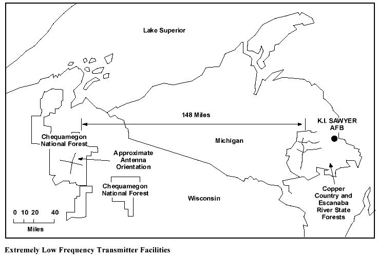
controlled by a submarine BCA. The two ELF transmitter facilities are located at Clam Lake,
Wisconsin and Republic, Michigan. The location of these transmitter facilities are illustrated in
Figure B-1.
 This unique communication system is designed to transmit short alerting messages to submarines
operating far below the ocean surface. The ELF frequencies used, in the 40–80 Hz range, were
selected for their long range signal propagation (i.e., global) and ability to penetrate seawater to
depths several hundred feet below the surface. In addition to the inherent covertness this
communication system provides, it also provides the submarine Commanding Officer with
operational flexibility to remain at required mission depth and speed. The ELF communication
system is used as a “bellringer” to notify the submarine crew to come shallow to copy a higher
data rate broadcast (e.g., SSIXS). At present, POM funding is provided for two site ELF
operation.
COMSUBLANT in Norfolk, Virginia and COMSUBPAC in Pearl Harbor, Hawaii alternate as
the ELF BCA. The BCA injects messages generated by the Submarine Operating Authorities
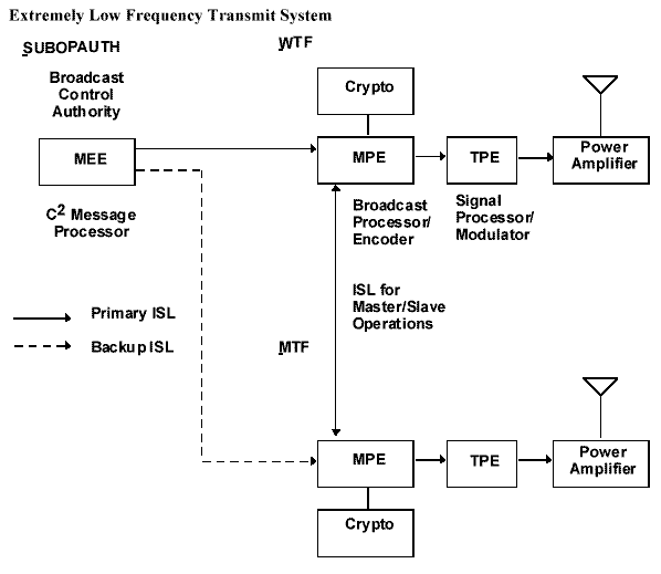
(SUBOPAUTHs) into the ELF system via the C 2 processor known as the Message Entry
Operator Terminal (MEOT). These messages are relayed to the transmit sites by dedicated
communication links, usually leased telephone lines, called intersite links (ISLs). At each
transmitter site, the messages received over the ISLs are decrypted and input into the Message
Processing Element (MPE). The MPE develops the ELF broadcast by encoding, queuing, and
encrypting the messages to be transmitted. The Transmit Processor Element (TPE) produces the
drive signals for the power amplifier and antenna. A simplified block diagram of the ELF
transmit system is shown in Figure B-2.

B.2.2 Extremely Low Frequency Biological/Ecological Monitoring and Interference
Mitigation
The ELF ecological monitoring program is an independent evaluation of the possible hazards
ELF RF transmissions may have on the environment. Sampling and gathering of data was
completed at the end of FY93 with review and comments on the resultant data by the National
Academy of Sciences expected during FY96. The ELF interference mitigation efforts fund the
procurement and maintenance of devices used to ground electrical voltages induced in long
metal inductors (e.g., wire fences, cable lines) in areas adjacent to the Wisconsin and Michigan
ELF radio transmitters.
B.2.3 Extremely Low Frequency Enhanced Data Rate
The ELF system provides the capability of sending short, highly formatted messages from the
single continental U.S. (CONUS) transmitter facility (dual transmitter sites) to submarines at
speed and depth operating essentially world wide. An Enhanced Data Rate (EDR) ELF system
was successfully demonstrated on a deployed submarine during the first quarter of FY95. The
EDR for ELF permits the use of longer messages (4 or 13 times the present message length) to
slightly shorter ranges in the same time as presently required for the existing LDR system. The
ELF EDR system has not been approved for fleet installation and is pending acceptance/funding.
B.2.4 Very Low Frequency/Low Frequency
The Navy shore VLF/LF transmitter facilities transmit a 50 baud submarine command and
control broadcast which is the backbone of the submarine broadcast system. The VLF/LF radio
broadcast provides robustness (i.e., improved performance in atmospheric noise), availability,
global coverage, and has seawater penetrating properties. The submarine VLF/LF broadcasts
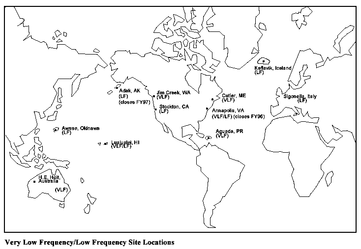
operates in a frequency range from 14 to 60 kHz and consists of six high powered, multi-channel
MSK Fixed VLF (FVLF) sites and seven multi-channel LF sites located worldwide. Figure B-3
lists the VLF/LF site locations. As part of the FY94 Base Realignment and Closure (BRAC),
Navy Radio Transmitter Facility (NRTF) Annapolis is planned for closure in FY96 and NRTF
Adak is planned for closure in FY97.

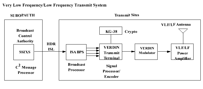
 Figure B-4 shows a simplified block diagram of the VLF/LF transmit system. The submarine
VLF/LF broadcasts are generated by the BCA or Alternate BCA from messages created locally
by the C 2 processor, the SSIXS processor, or accepted for relay by the SUBOPAUTH. The
BCAs and Alternate BCAs are connected to the transmitter sites by dedicated ISLs with the
ability for JCS and USSTRATCOM to seize BCA, at any time, for EAM dissemination. At each
of the transmitter sites, messages received over the ISLs are decrypted and input into the
Integrated Submarine Automated Broadcast Processor System (ISABPS). Submarine VLF/LF
broadcasts a continuous transmission sequence of prioritized messages which normally lasts two
hours. It is generated by ISABPS and sent to the VERDIN transmit terminal. The VERDIN
transmit terminal is used to multiplex, encrypt, encode, and modulate up to four 50 bps
submarine broadcast channels into VLF/LF radio frequency signals which is amplified/radiated
by the VLF/LF transmitter antenna.
B.2.5 Fixed Very Low Frequency Site Upgrades
This program maintains and upgrades antennas and transmitters at the FVLF sites. It consists of
three individual programs: (1) The Solid State Power Amplifier-Receiver (SSPAR) program;
(2) the Transmitter Keep-Alive Program (TKAP)/Service Life Extension Program (SLEP); and
(3) Antenna Maintenance Program (AMP).
The SSPAR program could modernize the FVLF transmitter sites with solid state technology.
This program could replace the current inefficient, unsupportable vacuum tube amplifiers and
provide standardization for FVLF sites. The SSPAR program execution is being evaluated.
SLEP is an interim program to extend the useful life of existing FVLF/LF equipment and
systems until the delivery of SSPAR. The SLEP improvements includes switchgear, circuit
breakers, solid state Intermediate Power Amplifiers (IPAs) and pre-IPAs, assorted electrical
components, and updated technical manuals. SLEP has been completed at Jim Creek, Lualualei,
Cutler FVLF, and Aguada, PR. H.E. Holt is scheduled to be accomplished in FY98.
The AMP is administered by the Commander, Naval Computer and Telecommunications
Command (NCTC) and provides for the ongoing maintenance and repair of FVLF/LF antennas
and antenna components (e.g., insulators, top hats, guy wires, etc.).
As part of the overall DOD shore infrastructure reduction, NCTC and SPAWAR are examining
modernization and cost savings alternatives within the submarine VLF/LF FSBS that could be
accomplished which would maximize the return on initial investment. These study efforts,
called the Smart Resource Management System (SRMS), are centered around consolidation of
the shore VERDIN ISABPS equipment and more cost effective connectivity from the
BCA/Alternate BCA to the BKSs and Broadcast Transmitting Stations (BTSs). Other initiatives
being considered are Remote Transmitter Operation, Range Extension Mode, Power
Management, Dynamic Channelization, and Split Array operation at the VLF sites.
B.2.6 Fixed Submarine Broadcast System Consolidation
CNO (N61) has tasked NCTC (N33) and SPAWAR PMW 173/PMW 172 to examine various
cost savings alternatives for the submarine VLF/LF FSBS. An outgrowth of this initiative is the
Consolidated Fixed Submarine Broadcast System (FSBS) which consists of two specific
elements: connectivity cost savings and BKS consolidation. Implementation of the FSBS
consolidation and cost savings is planned in three phases. During Phase I, WAN analysis and
connectivity for the FSBS will be evaluated and demonstrated. This effort is scheduled to
commence in FY96. Phase II is the design/validation phase of the Consolidated FSBS which
will subsequently be followed by Phase III in which actual deployment and installations occur.
B.2.6.1 Connectivity Cost Savings
The purpose of this effort is to replace costly existing dedicated leased lines which provide
connectivity between the BCA, BKS, and BTS. Use of existing DISN WANs, combined with
short leased “tail circuits” between the nearest WAN node and BCA, BKS, or BTS locations,
should significantly reduce these costs.
B.2.6.2 Broadcast Keying Station Consolidation
This effort consolidates the BKSs and the VERDIN ISABPS suites which key the transmitters,
typically located at the transmitter site, to a smaller number of centralized locations. The current
proposal being investigated would provide two consolidated keying stations on each coast. Each
consolidated keying station would have the ability to drive any transmitter supporting that
corresponding ocean area, providing some measure of reliability in the event one keying site
were out of commission. Since, each BKS requires communication links to each transmitter site,
connectivity costs using leased lines would make this consolidation impractical were it not for
the reduced operating costs realized by using a WAN (such as the DISN-IP Network, formerly
called the NAVNET Network). This proposal does incur initial costs to relocate the ISABPS
suites, but saves money by reducing BKS operational personnel and training schools. These cost
savings and payback period are being evaluated to determine the feasibility of this concept.
ISABPS processor upgrades and the use of COTS routers to automatically relay broadcast traffic
around network failures are also being considered.
B.2.6.3 Additional Fixed Submarine Broadcast System Cost Reduction Efforts
An additional concept which supports the cost reduction initiatives of the FSBS consolidation is
remote transmitter operation. NCTC (N33) has funded a prototype Remote Control System
(RCS) based on commercial radio broadcast controllers and is undergoing evaluation at the
Lualualei FVLF transmitter. Technical issues, including remote control of the transmitter
antenna parameters and off the air monitoring of the broadcast, remain to be resolved before a
complete remotely-operated BTS is feasible. Program plans are to submit required funding for
RCS as part of the Consolidated FSBS POM 98 submittal.
Power management of VLF/LF transmitters will make use of a computer hosted propagation and
noise model to aid operators in assessing power required by a transmitter given the time of the
year/day and geographic area needing VLF/LF broadcast coverage. A related benefit of this
initiative is computer produced VLF/LF coverage prediction charts based on time of day and
transmitter frequency that can be used by Fleet operators. Through this program, cost savings
will be realized through the efficient use of transmitted power ensuring lower fuel and power
bills and accurate VLF/LF coverage predictions.
VLF/LF Range Extension Mode would leverage RDT&E work that was performed at NRaD,
San Diego, CA. The premise of Range Extension is that less transmitter power is required for
the submarine shipboard VLF/LF receiver to receive the transmitted signal because it takes
advantage of signal encoding and compression techniques. This capability would be
implemented through VERDIN software changes at the shore transmitters and shipboard
receivers.
Dynamic Channelization will provide submarine broadcast flexibility and potential cost savings
by allowing a 4 channel VLF/LF broadcast to be reconfigured to either a 2 or 1 channel VLF/LF
broadcast. Cost savings may be realized when operating either the 2 or 1 channel VLF/LF
broadcast because less transmitter power is required as there is more energy per bit in the given
data stream.
Split Array VLF transmitter operation would allow for the transmission of two separate
submarine broadcasts on different VLF frequencies. Besides broadcast flexibility, small saving
may be accrued through lower transmitter power required at each transmitted frequency.
B.2.7 Take Charge and Move Out (TACAMO)
The Navy TACAMO program provides for survivable VLF/LF MEECN mode, HIDAR, and
EHF transmissions during trans-attack and post-attack phases. The TACAMO program is
managed by the Naval Air Systems Command and provides fleet support for two squadrons
totaling 16 E-6A aircraft and a wing component located at Tinker Air Force Base, Oklahoma
City.
The TACAMO program focuses on three primary areas: airframe procurement and maintenance,
communications equipment integration (e.g., MILSTAR), and TACAMO-unique
communications equipment (e.g., High Power Transmit System (HPTS), Long Dual Trailing
Wire Antenna (LDTWA)).
As part of the DOD Airborne Command and Control consolidation, the Navy E-6A aircraft has
been chosen as the common airframe to accommodate the USSTRATCOM battle staff and
provide command and control communications to all three legs of the strategic triad. Funds
required for modification of the E-6A communication and staff capabilities will be provided by
retiring Air Force EC-135 aircraft. The TACAMO/Airborne Command Post (ABNCP)
integrated aircraft nomenclature will be the E-6B.
B.2.8 Integrated Very Low Frequency Digital Interface Network Transmit Terminal
Integrated VERDIN Transmit Terminal (IVTT) replaces the aging VERDIN transmit/modulator
terminals (AN/URT-30) at VLF/LF shore sites and provides equipment for emergent new shore
site requirements. IVTT consists of: EVS control unit, modified electronic enclosure shelf,
existing NDI processor (ISABPS PIP - AN/UYK-83), and Navy Research Laboratory (NRL)
developed modulator.
B.2.9 AN/FRT-95(A) Low Frequency Transmitter
The AN/FRT-95(A) program will provide four 250 kW solid state LF transmitters. Sites planned
to receive the new LF transmitters are: Aguada, PR; Keflavik, Iceland; Awase, Okinawa; and
Sigonella, Italy. The LF solid state transmitter upgrades will improve area coverage in the
Northern Atlantic and Northern Pacific regions. Testing of the first AN/FRT-95 (A) solid state
LF transmitter has been successfully completed at the Aguada, PR transmitter site. The
AN/FRT-95(A) transmitter installation and antenna upgrades at Iceland were completed in FY95
while those at Awase, Okinawa are planned to be completed in early FY98.
B.2.10 Submarine High Frequency
The Submarine shore HF infrastructure is operated and maintained by the Commander, NCTC
and consists of eight HF receiver sites and eight HF transmitter sites. The HF receiver sites
support the submarine Circuit Mayflower and Clarinet Merlin systems while the HF transmitter
sites rekey the Strategic SSBN submarine broadcast. Functional control of the Clarinet Merlin
and Circuit Mayflower programs are in process of being transferred to the Submarine TYCOMs.
COMSUBLANT/COMSUBPAC will assume the lead responsibility for operation of the Circuit
Mayflower and Clarinet Merlin Systems in their respective AORs. Naval Computer and
Telecommunications Area Master Station, Atlantic (NCTAMS Lant) will maintain responsibility
for maintenance of the Circuit Mayflower System worldwide. This transfer will start mid FY96
and be completed during FY97.
B.2.11 Submarine Satellite Information Exchange System
The SSIXS program provides UHF SATCOM capability at high data rates (currently 4800 baud)
to deployed submarines. The SSIXS UHF SATCOM broadcasts are formed by the SSIXS
computer operators at each of the four Submarine BCAs or their designated alternates. The
SSIXS computer is also used to assemble the FVLF/LF broadcast, which is relayed to ISABPS
for storage and transmission via the FVLF/LF transmitters. The SSIXS broadcast information is
forwarded to the appropriate NCTAMS which transmits, receives, and relays satellite
communication. The system uses the Navy’s FLTSAT satellites and will transition to UHF
DAMA capability when the total Military SATCOM (MILSATCOM) architecture transitions.
An ongoing upgrade program, SSIXS II, has completed its initial hardware and software
upgrades and is providing evolutionary enhancements via software revisions. Future capabilities
will include screen-on-the-fly (multicast) for improved efficiency and reduced downlink time.
B.2.12 Officer in Tactical Command Information Exchange System
The submarine OTCIXS program provides tailored OTH-T information through a UHF
SATCOM channel to submarines at high data rates (2400 baud). This broadcast is assembled at
the submarine Shore Targeting Terminals (STTs) located at the submarine BCAs and then
relayed to a supporting NCTAMS for transmission, as with SSIXS. The submarine OTCIXS net
differs from the Surface OTCIXS in one way. The submarine OTCIXS broadcast is a
“protected” broadcast, similar to the submarine SSIXS broadcast, while the Surface OTCIXS net
is not. Both surface and submarine OTCIXS nets use KG-84s.
In addition to OTH-T information, this link is also used to relay TOMAHAWK MDUs and
TADIXS A information to submarines not currently equipped with TD-1271 DAMA modems
(DAMA TEMPALT). As with SSIXS, submarine OTCIXS will transition to UHF DAMA.
B.2.13 Tactical Digital Information Exchange Subsystem A and B
TADIXS A provides the surface Navy, via a UHF DAMA circuit, a 2400 bps link used for
MDUs and other file transfers. Following installation of Mini-DAMA and upgrades to the ON-143(
V)6 firmware, SSNs will be able to receive TADIXS A, providing commonality with the
surface navy. In the interim, SSNs equipped with the TD-1271 DAMA modem TEMPALT and
KG-84A cryptographic devices can receive TADIXS A information. TADIXS B supports near
real-time relay of intelligence data and requires installation of the TRE (AN/USQ-101), currently
programmed for SSNs and discussed in section 4.2.1.3, Shipboard Transmitters and Receivers
and Appendix A.
B.2.14 Strategic Communications Continuing Assessment Program/Fleet Ballistic Missile
Continuing Evaluation Program
The Strategic Communications Continuing Assessment Program (SCAP) and FBM CEP are
administered by JHU/APL as an independent agent for CNO and the Operational Commanders.
The FBM CEP program evaluates communication links to SSBN submarines and reports:
communications performance, identifying trends in material and operational performance,
training deficiencies, material problems, and provides aid in developing operational doctrine.
The SCAP performs qualitative and quantitative assessments of existing and planned strategic
communications systems for the delivery of EAMs to SSBN submarines.
B.2.15 North Atlantic Treaty Organization/Allied Communications Interoperability
Alliance solidarity is a key to national defense strategy and, as would be expected, drives a key
interest in bilateral and multilateral submarine operations and communications. As with the
U.S., VLF/LF communications is the backbone of NATO submarine command and control.
Within technology transfer and funding constraints, NATO has embarked upon a VLF/LF
communications program modeled after the U.S. FSBS. To be interoperable with the NATO
submarine broadcast, the U.S. has modified the submarine shipboard VERDIN receivers and one
channel of the shore transmitter sites at Cutler, ME and Aguada, PR to be STANAG 5030 MSK
waveform capable. The Vinson UHF secure voice system and its KY-58 crypto provide a
NATO/Allied interoperable LOS voice circuit for submarines.
B.2.16 Submarine Broadcast Control Authority Modernization
To support the shift in submarine mission emphasis and to operate efficiently and cost
effectively, the Submarine Operational Commander’s Command and Control facilities must be
modernized and kept compatible with submarine shipboard and Joint Task Force C 2 systems.
Submarine shore BCAs and their alternates require information transfer and processing systems
that are highly automated and modern. These systems must leverage existing commercial
technology so that BCA manning may be reduced and accompanying life cycle maintenance and
logistic support costs are kept to a minimum. The BCA modernization efforts must address
methods to effectivly consolidate BCA operator actions and fuctions. Seamless interoperability
with the GCCS and DMS is essential.
As the single point of contact for all submarine C 4 I matters, SPAWAR PMW 173 has been
directed to develop a plan to modernize and maintain the submarine BCAs based on TYCOM
requirements submitted to CNO N87. CNO N87 is the sponsor for the submarine BCAs and will
address funding for modernizing and maintaining the BCAs during POM 98.
B.2.17 Submarine Support Tender Communications Modernization
Submarine Tenders (ASs) support both tactical and strategic communications requirements and
require continuing modernization efforts to ensure interoperability. As submarine force assets,
Tenders are sponsored by CNO N87. CNO N87 and N6 will coordinate to address funding to
ensure Tenders are included in the Fleet Modernization Program (FMP) and receive standard
communications suite upgrades.


