 Fighting Proliferation
Chapter 5
This assessment examines the proliferation of space technology from traditional centers such as the United States, Western Europe, and the former Soviet Union to nontraditional areas in the Far East, South Asia, the Middle East, Africa, and South America. It evaluates the direction, content, and potential impact of this technology flow and in so doing challenges conventional wisdom on satellites and proliferation, including the following:
1. Civilian satellites and space programs represent peaceful technology—they are not militarily significant.
2. The few satellites that are militarily significant are made by the US; the few other nations that can field military satellites are our North Atlantic Treaty Organization (NATO) allies and Japan.
3. Even if third world countries want to use space for military purposes, we needn’t worry because it will cost them billions of dollars to make systems of their own, and access to others’ systems will not help them achieve a military capability.
By way of preliminary observations, one may note the following:
1. Critical parameters and performance figures for the major subsystems and components frequently overlap or are identical in civil and military space systems; civil space systems have already demonstrated substantial military utility; imaging systems are moving toward higher resolution and faster data delivery; and communications satellites (COMSAT) have a high degree of crossover.
2. The US and its Western allies no longer hold an exclusive monopoly on space technology; the proliferation of space technologies will pose an increasing problem for policymakers.
3. Several factors are serving to mitigate the cost barriers to acquiring significant space capabilities: foreign government spending on space has already reached substantial levels; cooperative and cost-sharing agreements have reduced individual countries’ cost of access to space; the cost of acquiring some capabilities is declining rapidly; and the proliferation of many space technologies and their inherent dual-use capability will pose problems for US strategic and tactical forces and will complicate US planning in future military engagements.
The US recently relaxed policy limits on the resolution of commercial remote-sensing systems. In response, several commercial imagery systems will be launched in the next several years with resolution in the range of one to three meters (table 5.1).* These systems will also possess substantial tasking capability, allowing a region of particular interest to be imaged every two days—or more frequently. One result is that, in future military crises, US and allied troop deployments can be imaged on a near-daily basis. So-called shutter control of US systems may reduce this threat, but as we will demonstrate, a number of non-US systems may not be subject to the same shutter control.
*Unless otherwise noted, all tables and illustrations courtesy Berner, Lanphier, and Associates, Inc., 105A West Edmonston Drive, Rockville, Maryland 20852 (1995).
Table 5.1
Characteristics of Planned
US Commercial Imagery Systems
| SYSTEM | LAUNCH | RESOLUTION | SWATH | TASKING | STEREO | REVISIT | GEODETIC ACCURACY |
|---|---|---|---|---|---|---|---|
| World View | 1995 | 15 meters (m) (multispectral) 3 m pachromatic (pan) |
3 X 3 kilometers (km) | ±30º (along and x-track) | Yes | 20 days (no tasking) five days (tasking, equatorial) | 50 m |
| Eyeglass | 1997 | 1 meter (pan) | 15 km |
±45º (along and x-track) |
Yes | two days or less | 100 m |
| Space Imaging System | 1997 | 4 meters (multispectral) 1 m (pan) | 15 km |
±30º (along and x-track) |
Yes | two days or less | 15 m |
With stereo capability and geodetic accuracy of 15 to 100 meters, the imagery from commercial systems can also support non-time-critical military applications such as developing a target set for ballistic missiles. Here, the activity may take place over a long time period prior to any crisis or outbreak of hostilities. For such applications, shutter control does not appear to provide a useful solution.
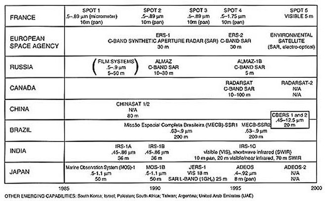
Even if current policy guidelines mitigate the threat posed by US commercial imagery systems, a growing number of foreign imagery systems are not subject to US control (table 5.2). France, Russia, the European Space Agency, Canada, Israel, China, India, Brazil, and Japan all will be operating space-based imagery systems during the second half of this decade. Other countries have sought to purchase imagery systems from US or European suppliers. This is a fundamental change from the situation in the early 1980s when the US and Soviet Union were the only countries with any meaningful satellite-imagery capability.
Table 5.2
Current and Planned
Foreign Remote-Sensing Systems
France was the next country after the US and Soviet Union to field a significant space-imagery capability. The French satellite pour l’observation de la terre (SPOT) system (table 5.3) was the first civil/commercial system to use solid-state charge-coupled devices (CCD) as detectors. This was an important advance because CCDs improve the sensitivity of the sensor and thus allow the ground resolution to be improved. SPOT 1’s 10-meter panchromatic imagery was a marked improvement relative to land satellite’s (LANDSAT) 30-meter resolution and represented the best resolution available from a civil/commercial electro-optical imagery system.
| WEIGHT (KILOGRAMS [kg]): | 1, 2, 3-1, 750; 4-2,500 |
| POWER (WATTS [w]): | 1, 2, 3-1, 900 END OF LIFE; 4-2,200 END OF LIFE |
| DESIGN LIFE (YEARS): | 1, 2, 3-2 YEARS; 4-5 YEARS |
| LAUNCH DATE: | 1-1986; 2-1990; 3-1993; 4-1995 |
| STABILIZATION ACCURACY (DEGREES): | 1, 2, 3-0.1; 4-0.03 |
| ALTITUDE (km): | 832 |
| GROUND-TRACK REPEAT (DAYS): | 26 NADIR (369 ORBITS); 2-5 OFF NADIR |
| INCLINATION (DEG.): | 98.7 |
| SENSOR: | HIGH RESOLUTION VISIBLE (HRV) MULTISPECTRAL | HRV PANCHROMATIC |
| POWER (w): | 95 | 95 |
| WEIGHT (kg): | 241 | 241 |
| SPECTRAL REGIONS (MICRONS): | (A) .50-.59 | .51-.73 |
| (B) .61-.68 | ||
| (C) .79-.89 | ||
| (D) 1.58-1.75 (SPOT 4 ONLY) | ||
| SWATH WIDTH (km) | 60 | 60 |
| GROUND RESOLUTION (m) | 20 | 10 |
| NUMBER OF DETECTORS: | 1,728/CHIP | 1,728/CHIP |
| 3,000/LINE | 6,000/LINE | |
| DETECTOR TYPE: | SILICON CHARGE-COUPLED DEVICES (CCD) | SILICON CCD |
| DETECTOR SIZE (MICRONS): | 13 X 13 | 13 X 13 |
| QUANTIZATION LEVELS: | 256 | 64 |
| RADIOMETRIC SENSITIVITY: | (A) 10 < SIGNAL/NOISE RATIO (S/N) < 212 |
6 < S/N < 233 |
| (B) 5 < S/N < 230 | ||
| (C) 5 < S/N < 214 | ||
| BAND-TO-BAND REGISTRATION (m): | 6 | 25 |
| SENSOR DATA RATE (MEGABITS PER SECOND [Mbps]): | 25 | 25 |
| STEREO IMAGING: | YES | YES |
| OFF-NADIR VIEWING: | YES | YES |
The greatest interest is in electro-optical systems and, as we discuss later, synthetic aperture radar (SAR) systems. However, the Russians continue to provide film-based imagery for commercial use (table 5.4). Some of these systems actually provide the best spatial resolution available today from civil/commercial systems. They are well matched to such applications as mapping or targeting of fixed targets. With a typical on-orbit life of one month and revisit time of 14 days, however, each satellite provides only two passes over a given area. Thus, multiple satellite launches are needed to provide ongoing coverage of a continuing crisis or conflict.
Table 5.4
Russian Film-Retrieval Systems
| PLATFORM | COSMOS (VARIANT 1) | COSMOS (VARIANT 2) | MANNED ORBITAL STATION | ||
|---|---|---|---|---|---|
| REVISIT (DAYS) | 14 | 14 | 14 | ||
| LIFE (MONTHS) | 1 | 1 | 1 | ||
| ALTITUDE (km) | 230-240 | 180-450 | 300 | ||
| INCLINATION (DEGREES) |
82 | 82 | 51.2 | ||
| CAMERA TYPE | KFA-1000 | KATE-200 | MK-4 | KATE-140 | MKF6M |
| WIDTH (km) (200 km ALTITUDE) |
120 | 180 | 120 | 380 | 190 |
| F (MILLIMETERS[mm]) |
1,000 | 200 | 300 | 140 | 125 |
| FRAME SIZE (mm) | 300 x 300 | 180 x 180 | 180 x 180 | 180 x 180 | 56 x 81 |
| NUMBER OF BANDS | 2 | 3 | 4 OF 6 | 1 | 6 |
| BANDS | 570-580 680-810 |
500-600 600-700 700-900 |
635-690 515-565 580-580 810-900 460-505 400-700 |
VISIBLE | 460-500 520-560 580-620 640-680 700-740 780-860 |
| RESOLUTION | 5-10 | 15-30 | 5-8 | 50 | 20-50 |
| % OVERLAP | 60 | 20-80 | 60 | 20-80 | 20-80 |
| MAP SCALE | 1:200,000 | 1:100,000 | 1:600,000-1:150,000 | 1:210,000 | 1:240,000 |
A key factor that increases the tactical military utility of satellite imagery is the ability to obtain imagery under all types of weather and illumination conditions. Electro-optical systems cannot provide day/night, all-weather imagery, but SAR systems can. The Russian ALMAZ is one example of a SAR system (table 5.5). ALMAZ advertised a resolution of 10 to 15 meters, but with its 15-meter-long antenna, it was capable of achieving 7.5-meter resolution. ALMAZ was capable of imaging any point on earth within one to four days under any weather or illumination condition. The Russians currently are looking for commercial partners to field the next ALMAZ system.
| WEIGHT (kg): | 18,300 |
| POWER (w): | |
| DESIGN LIFE (YEARS): | 2-3 |
| LAUNCH DATE: | 1991 |
| ALTITUDE (km): | 300 |
| REVISIT PERIOD (DAYS): | 1-4 (WITH TASKING) |
| INCLINATION (DEGREES): | 73 |
| SPATIAL RESOLUTION (m): | 10-15 |
| POLARIZATION: | HORIZONTAL |
| PULSE LENGTH (MICROSECONDS): | 70, 100 |
| AVERAGE POWER (w): | 80 |
| ANTENNA COMPOSITION: | SLOTTED WAVEGUIDE |
| SWATH WIDTH (km): | 45 |
| PULSE REPETITION FREQUENCY (PRF)(HERTZ [Hz]): | 3,000 |
| FREQUENCY: | 3 GIGAHERTZ (GHz) (C-BAND) |
| PEAK POWER (w): | 5,000 |
| LOOK ANGLE (DEGREES): | 30-60 OFF NADIR |
| BANDWIDTH (MEGAHERTZ[MHz]): | 17.32 |
| ANTENNA LENGTH (m): | 15 |
| ANTENNA WIDTH (m): | 1.6 |
The Canadian RADARSAT (table 5.6) is another example of a civil/commercial SAR imagery system. RADARSAT can image large areas under all types of weather conditions at a resolution of up to 10 meters. At northern latitudes, RADARSAT can provide imagery of a given location every three days. The combination of day/night, all-weather imagery and timely revisit capability makes SAR systems attractive for tactical imagery applications.
| WEIGHT (kg): | 4,000 |
| POWER (w): | 5,500 EOL |
| DESIGN LIFE (YEARS): | 5 |
| LAUNCH DATE: | 1995 |
| STABILIZATION ACCURACY (DEGREES): | 0.1 |
| ALTITUDE (km): | 777-804 |
| GROUND-TRACK REPEAT CYCLE: | 16 DAYS |
| GROUND COVERAGE CYCLE: | 1 - ARTIC; 3 - CANADA; 16 - GLOBAL |
| INCLINATION (DEGREES): | 98.5 |
| DATA RATE (Mbps): | 85 RECORDED - 105 DOWNLINKED |
| SPATIAL RESOLUTION (m): | 10-100 |
| WEIGHT (kg): | 385 |
| POLARIZATION: | HORIZONTAL/HORIZONTAL (HH) |
| PULSE LENGTH (MICROSECONDS): | 42 |
| AVERAGE POWER (w): | 300 |
| ANTENNA COMPOSITION: | 400-600 10w PEAK OUTPUT TRANSMIT/RECEIVE (T/R) MODULES |
| SWATH WIDTH (km): | 45-500 (ACCESSIBLE = 500-700) |
| PRF (Hz): | 1,270-1,390 |
| FREQUENCY: | 5.3 GHz (C-BAND) |
| PEAK POWER (w): | 5,000 |
| LOOK ANGLE (DEGREES): | 20-50 - 50-60 EXPERIMENTAL |
| BANDWIDTH (MHz): | 11.6, 17.3, 30 |
| SAMPLING RATE (MHz): | 12.9, 18.5, 32.3 |
| ANTENNA LENGTH (m): | 15 |
| ANTENNA WIDTH (m): | 1.6 |
OTHER SENSORS: ADVANCED ALONG=TRACK SCANNING RADIOMETER
ADVANCED RADAR ALTIMETER/OCEAN-WAVE SPECTROMETER
Japan’s Advanced Earth Observation System (ADEOS) (table 5.7) is an example of a non-US electro-optical system that combines fairly high resolution (eight meters, panchromatic) with very rapid revisit capability. ADEOS also provides imagery in a swath 80 kilometers wide, as opposed to the 15-kilometer-wide swath of US commercial systems, thus providing wider-area coverage than that available from US systems. Should the Japanese opt to lower ADEOS’s orbit for selected higher-resolution imagery, they can obtain resolution of about three meters. It is thus misleading to assume that foreign systems cannot match the performance of US commercial systems should they so choose.
| WEIGHT (kg): | 3,000 |
| POWER (w): | 3,500 |
| DESIGN LIFE (YEARS): | 3 |
| LAUNCH DATE: | 1996 |
| STABILIZATION ACCURACY (DEGREES): | |
| ALTITUDE (km): | 799.8 - SUN SYNCHRONOUS |
| GROUND-TRACK REPEAT (DAYS): | 41 |
| INCLINATION (DEGREES): | 98.6 |
| EQUATOR CROSSING TIME: | 10:30A.M. |
| SENSOR: | ADVANCED VISIBLE NEAR INFRARED (AVNIR) | OCEAN COLOR TEMPERATURE SENSOR (OCTS) |
| POWER: | 250 | 300 |
| WEIGHT (kg): | 200 | 260 |
| SPECTRAL CHANNELS: | (1) .4-.5 (2) .53-.62 (3) .62-.72 (4) .82-.92 (5) .52-.72 pan |
.402-.422 .510-.530 .433-.453 .555-5.75 .480-.500 .655-.675 .745-.785 .845-.885 3.55-3.85 8.25-8.75 10.5-11.5 11.5-12.5 |
| SWATH WIDTH (km): | 80 | 1,500 |
| GROUND RESOLUTION (m): | (1-4) 16 : (5) 8 | 700 |
| POINTING (DEGREES): | +/- 40 CROSS TRACK (XT) | +/- 20 IN TRACK (IT) |
| EARTH COVERAGE (DAYS): |
1 | 3 |
OTHER SENSORS: NATIONAL AERONAUTICS AND SPACE ADMINISTRATION (NASA) SCATTEROMETER (NSCAT) AND TOTAL OZONE MAPPING SPECTROMETER (TOMS)
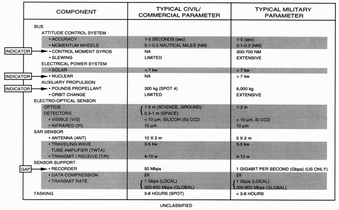
A comparison of civil/commercial parameters with military parameters for the same components reveals that no significant differences exist between figures of merit for the major segments of civil versus military remote-sensing systems (table 5.8). The figures of merit typical for such systems and components of civil and military imaging systems are virtually identical. The two types are distinguishable primarily by their configurations and orbits.
Table 5.8
Overlap of Subsystems and Technologies for Civil and Military Imaging
Systems
For example, civil imaging systems are not required to slew rapidly from target to target to meet military tasking requirements. They therefore would not normally make use of control moment gyros (CMG), whereas military imagers would. Fuel loads for attitude control and orbital maneuvers would also be larger for military systems than for their civil variants, and for some military systems (e.g., Soviet radar ocean reconnaissance satellites [RORSAT]), power is supplied by nuclear generators rather than solar panels.
The only military subsystem for which no comparable civil capability exists is the wideband-sensor data recorder found on some electro-optical and SAR imagers (fig. 5.1). We have found no Japanese supplier of such space-qualified recorders, and only one potential European source—Enertec—which has a wideband tape recorder under development. This difference would be significant were it not for the fact that both the Japanese and the Europeans are developing and will soon deploy relay satellites that will allow imagery gathered over a remote site to be transmitted in real time to a ground station instead of being recorded for later transmission.
The Hubble space telescope is an example of a high-performance, space-based imaging system using late 1970s US technology. If it were pointed at the earth, it could achieve a ground-sample distance (GSD—i.e., resolution) of five-hundredths of a meter (about two inches) from an altitude of 200 kilometers (km) (about 132 miles). Using the best currently available European and Japanese CCDs in the focal plane of a space-based, remote-sensing system, our notional design (table 5.9; table 5.10, right column) could achieve almost the same resolution. Fabricating the optical system for this sensor would be a challenge but within the range of capabilities of both the Japanese and Europeans. Similarly, both have—or are rapidly acquiring—the necessary capability to design, assemble, and operate such large space systems. The European Ariane V and the Japanese H-2 launchers could place the required mass and volume in orbit, and planned relay satellites would allow transmission of the imagery directly to national users. The US could not, through technology export controls alone, prevent the development or launch of such a system.
Table 5.9
Sample of Commercial Charge-Coupled Devices
| COUNTRY | COMPANY | ARRAY SIZE (NUMBER OF ELEMENTS) |
PIXEL SIZE MICROMETERS (µm) | |
|---|---|---|---|---|
| US | LORAL | 3,456 | 7 X 7 | |
| KODAK | 5,000 | 7 X 7 | ||
| KODAK | 3 X 8,003 | 9 X 9 | ||
| FRANCE | THOMSON | 4,096 | 7 X 7 | |
| THOMSON | 5,184 | 7 X 7 | ||
| THOMSON | 2,048 | 10 X 10 | ||
| JAPAN | NEC | 4,096 | 5 X 7 | |
| NEC | 2,560 | 5 X 7 | ||
| HITACHI | 5,006 | 7 X 7 | ||
| OKI | 4,096 | 7 X 7 | ||
| BELGIUM | IMEC | 1,024 | 4 X 4 | |
| IMEC | 1,728 | 6 X 6 |
| HUBBLE TELESCOPE (13 MICRON PIXELS) |
SYSTEM DESIGNED WITH CURRENT EUROPEAN OR JAPANESE DETECTORS |
|
|---|---|---|
| GDS (FROM 200 km) | 0.05 m | 0.06 m |
| PRIMARY MIRROR | 2.4 m F/3 |
2 m F/1.9 |
| SYSTEM FOCAL LENGTH | 57 m | 16.67 m |
| SPACECRAFT LENGTH | 13.16 m | 8 m |
| DRY WEIGHT | 11,000 kg | 6,500 kg |
There is a general tendency to be more concerned about foreign capabilities for imagery satellites than for COMSATs. Thus, export of technologies for COMSATs may not be subject to the same scrutiny as technologies earmarked for imagery systems. However, a number of components exported for COMSATs can also be used to build imagery satellites.
Such components include momentum wheels, which are electromechanical devices used on COMSATs to orient and stabilize the spacecraft body and antennas. On an imagery satellite, these devices fulfill the same function, but in doing so, they orient and stabilize the focal plane and optical train. To the extent that they can deliver a strong control force while using little power and keeping weight to a minimum, these devices have utility on military imagery satellites.
Momentum wheels commercially available from European sources have performance characteristics useful for imagery satellites (table 5.11). The German firm Teldix is exporting its DR50 momentum wheel to China for use on the DFH-3 COMSAT. That same momentum wheel is used by the Japanese for the attitude control of their MOS-1 imagery satellite. Even more capable commercial systems are available.
| TECHNICAL PARAMETER |
AEROSPATIALE (FRANCE) |
TELDIX (GERMANY) |
||
|---|---|---|---|---|
| MODEL NUMBER | RCPM-50 | RCPM-150 | DR50a | DR68 |
| NOMINAL AVERAGE MOMENTUM (NEWTON- METER-SECONDS [N-m-s]) |
50 | 150 | 50 | 68 |
| CONTROL TORQUE (NEWTON-METERS [N-m]) |
0.1 | 0.1 | 0.07 | 0.085 |
| MASS (kg) | 10.5 | 13.5 | 7.6 | 7.9 |
| DIAMETER (mm) | 350 | 350 | 347 | 347 |
| HEIGHT (mm) | 190 | 190 | 119 | 119 |
| NOMINAL POWER (w) | 6 | 10 | 9-16 | 9-16 |
| MAXIMUM POWER (w) | 110 | 150 | 53 | 90 |
a Used on MOS-1, DFH-3
Thus, foreign COMSAT programs (table 5.12) can serve as a vehicle for acquiring technologies that can be diverted to more worrisome reconnaissance applications. If an effective control regime is to be developed, policymakers must be aware of the potential applications of key subsystems and components (such as momentum wheels) as well as the overtly announced uses of complete systems.
Table 5.12
Europe and Japan Demonstrate Spacecraft System-Integration Capbilities
| EUROPE | JAPAN | ||
|---|---|---|---|
| ERS-1 | MULTIMISSION MICROWAVE AND SAR | ENGINEERING TEST SATELLITE (ETS)-VI | LARGE,COMPLEX RELAY SATELLITE |
| SPOT 1 and 2 | ELECTRO-OPTICAL | JAPAN EARTH REMOTE SENSING (JERS) | SAR, VISIBLE (VIS), SHORTWAVE INFRARED (SWIR) |
| INTERNATIONAL MARITIME SATELLITE (INMARSAT) | LARGE COMSAT | MARINE OBSERVA- TION SYSTEM (MOS) 1 AND 2 |
MIDSIZE ELECTRO-OPTICAL |
| EUROPEAN TELECOMMUNICATIONS SATELLITE (EUTELSAT) | LARGE COMSAT | ADVANCED EARTH OBSERVATION SYSTEM (ADEOS) | LARGE ELECTRO-OPTICAL |
| NATO IV | MILITARY COMSAT | ||
| ITALIAN SATELLITE (ITALSAT) | LARGE COMSAT | ||
| INTERNATIONAL SPACE OBSERVATORY (ISO) | IR TELESCOPE | ||
| ENVIRONMENTAL SATELLITE (ENVISAT) | LARGE, MULTISENSOR EARTH OBSERVATION | ||
| HELIOS | MILITARY/INTELLIGENCE ELECTRO-OPTICAL | ||
A unilateral space-technology nonproliferation regime is not a viable policy option, because no one nation now has unique control over all critical space technologies. A number of countries possess capabilities in some of the systems and components utilized in militarily significant satellites (table 5.13). The US has capabilities in all of these fields.
Table 5.13
Unilateral Control of Key Subsystems and Components
Not a Viable Policy
Option
| FRANCE | GERMANY | UNITED KINGDOM |
OTHER EUROPEAN COUNTRIES |
JAPAN | |
|---|---|---|---|---|---|
| ELECTRO- OPTICAL (EO) SENSORS |
Matra | MBB | EEV | Phillips | NEC Fujitsu |
| OPTICS | Reosc Angeniex Bertin et Cie Matra Sodem |
Zeiss Schott Hareus |
Cranfield | Ohara Glass Tokyo Opto- Electronics |
|
| VISIBLE DETECTORS |
Thomson | Valvo | EEV | IMEC Catholic University Phillips |
Melco NEC Hitachi Toshiba Fujitsu Oki |
| IR DETECTORS |
SAT Thomson Sofradir CEA |
Valvo AEG Telefunkun |
Royal Signals Mullard |
Phillips IMEC |
Fujitsu NEC Melco Toshiba |
| SAR SENSORS |
Alcatel Dassault |
Dornier DLR |
Marconi | Technical University of Denmark (Air) Selenia Spazio |
Melco |
| ANTENNA | Alcatel | Dornier | Marconi | Melco | |
| TRAVELING WAVE TUBE AMPLIFIER (TWTA) |
Thomson | AEG Telefunken Siemens |
Marconi Ferranti Thorn |
Toshiba Nec |
|
| TRANSMIT/ RECEIVE (T/R) MODULES |
Alcatel Thomson |
Plessey/ Marconi |
AME Space (chirp modules) |
Fujitsu Toshiba NEC Melco |
|
| ATTITUDE SENSORS |
Sodem Sagem |
MBB (star) | Ferranti (gyro) SIRA (star) Marconi |
Toshiba NEC Melco |
|
| ACTUATORS | Aerospatiale | Teldix | Marconi BAe |
Melco IHI |
|
| ATTITUDE CONTROL SYSTEM (ACS) |
Matra Sodern |
Dornier MBB |
BAe | Melco Toshiba |
|
| ELECTRICAL POWER SYSTEM (EPS) |
SAFT Aerospatiale |
Telefunken MBB |
BAe | Toshiba Sharp |
|
| PROCESSORS | DLR | Ferranti (ASARS) Marconi |
MDD Spar Norsk |
Fujitsu NEC |
Starting in the early-to-mid 1970s, the nations of Europe and Japan began to develop internally—and purchase externally—the capability to build key subsystems and components for space systems. That process is virtually complete; the Europeans and Japanese are currently marketing state-of-the-art satellite componentry. Thus, any hope that the US might have had of imposing unilateral control over foreign space programs by limiting the export of key components is virtually gone. If such controls are to work in the future, they must include the active participation of Europe and Japan in the control regime.
There is a natural tendency to define the national security sensitivity of a civil remote-sensing system in terms of its resolution. Those characteristics of a system that allow for high resolution are technically demanding. They include large optical trains, precise attitude control and stabilization of the spacecraft, and high data-rate transmission from the spacecraft to the ground. These technical characteristics easily distinguish highly capable spacecraft and sensors from ones that are less capable.
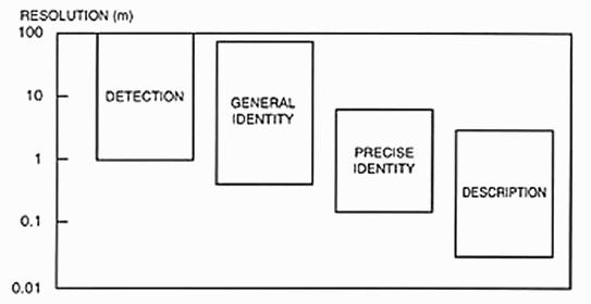
Certain resolution values are necessary to perform the required military tasks of detection, general identification, precise identification, and description (table 5.14, fig. 5.2). The current civil remote-sensing systems—LANDSAT and SPOT—directly supported military planning and operations during the Gulf War. The trend toward improving the resolution of foreign remote-sensing satellites will increase the military utility of these systems.
Table 5.14
Civil Remote-Sensing Systems: Improved Resolution
Increases Intelligence Capability (U)
| OBJECT | DETECTION | GENERAL IDENTITY |
PRECISE IDENTITY |
DESCRIPTION |
|---|---|---|---|---|
| BRIDGE | 6.1 | 4.6 | 1.5 | 0.9 |
| COMMUNICATIONS RADAR | 3 | 0.9 | 0.3 | 0.15 |
| COMMUNICATIONS RADIO | 3 | 1.5 | 0.3 | 0.15 |
| SUPPLY DUMP | 1.5 | 0.6 | 0.3 | 0.03 |
| TROOP UNITS | 21.3 | 2.1 | 1.2 | 0.3 |
| AIRFIELD FACILITIES | 6.1 | 4.6 | 3 | 0.3 |
| ROCKETS AND ARTILLERY | 0.6 | 0.3 | 0.15 | 0.05 |
| AIRCRAFT | 4.6 | 1.5 | 0.9 | 0.15 |
| COMMAND AND CONTROL HEADQUARTERS | 3 | 1.5 | 0.9 | 0.15 |
| MISSILE SITES (SURFACE- TO-SURFACE MISSILE [SSM], SURFACE-TO-AIR MISSILE [SAM]) |
3 | 1.5 | 0.6 | 0.3 |
| SURFACE SHIPS | 7.6 | 4.6 | 0.6 | 0.3 |
| NUCLEAR WEAPONS COMPONENTS | 2.4 | 1.5 | 0.3 | 0.03 |
| VEHICLES | 1.5 | 0.6 | 0.3 | 0.05 |
| LAND MINEFIELDS | 9.1 | 6.1 | 0.9 | 0.03 |
| PORTS AND HARBORS | 30.5 | 15.2 | 6.1 | 3 |
| COASTS AND LANDING BEACHES | 30.5 | 4.6 | 3 | 1.5 |
| RAILROAD YARDS AND SHOPS | 30.5 | 15.2 | 6.1 | 1.5 |
| ROADS | 9.1 | 6.1 | 1.8 | 0.6 |
| URBAN AREA | 61 | 30.5 | 3 | 3 |
| TERRAIN | — | 91.4 | 4.6 | 1.5 |
SOURCE: Senate Committee on Commerce, Science, and Transportation, 1978 NASA Authorization (Washington, D.C.: Governement Printing Office, 1977), pt. 3, 1597.
But resolution is only one measure of the utility of civil remote-sensing satellites. Also important are the spectral coverage of the imagery and the timeliness of the delivery of data to the user.
The US LANDSAT system provides multispectral imagery. LANDSAT spectral bands were selected with specific civil and scientific tasks in mind, such as estimating crop yields and environmental change. These bands were not selected to support military tasks.
Nevertheless, LANDSAT’s multispectral capability serves multiple military planning and operations requirements. Virtually all of the spectral regions included in civil systems (combined with specific resolutions) can support military tasks (table 5.15). For example, multispectral capabilities for vegetation analysis can also be used to support military terrain-delineation analysis and camouflage-detection tasks. LANDSAT imagery is currently being used to support Air Combat Command mission-critical requirements.
Table 5.15
Civil and Military Uses of Multispectral Imagery (U)
| APPLICATION | SPECTRAL BANDS | MILITARY UTILITY |
||||
|---|---|---|---|---|---|---|
| VISIBLE | NEAR INFRARED |
THERMAL INFRARED |
SAR | MICROWAVE | ||
| SOIL FEATURES |
X (30 m) |
X (30 m) |
- TERRAIN DELINEATION - ATTACK PLANNING - TRAFFIC- ABILITY |
|||
| SURFACE TEMPERATURE |
X (30 m - 1 km) |
X (1-4 km) (OCEAN) |
- ANTISUB- MARINE WARFARE (ASW) SUPPORT - TRAFFIC- ABILITY - AIRFIELD ANALYSIS |
|||
| CLOUDS | X (1-50 km) |
X (1-50 km) |
- WEATHER - ATTACK PLANNING |
|||
| SNOW ANALYSIS |
X (30 m - 1 km) |
X (1 km) |
- AREA DELINEATION - ATTACK PLANNING |
|||
| SURFACE ELEVATION |
X (5-10 m) (STEREO) |
- MAPPING - TERRAIN CONTOUR MATCHING - FLIGHT SIMULATION |
||||
| OCEAN-WAVE ANALYSIS |
X | - ASW | ||||
| ICE ANALYSIS |
X (15-100 m) |
X | X (1-5 km) |
- NAVIGATION - ASW SUPPORT |
||
| WATER ANALYSIS |
X (30 m - 1 km) |
X (30 m - 1 km) |
X (30 m - 1 km) |
- AMPHIBIOUS ASSUALT LANNING |
||
| CULTURAL FEATURES |
X (5-30 m) |
- TARGETING - BOMB DAMAGE ASSESSMENT |
||||
Senior US Air Force officials have stated that in the Gulf War, LANDSAT multispectral imagery was used for scene- change detection, terrain traffic analysis, invasion planning (“Can we drive tanks and trucks or drop airborne troops in a given region?”), and mapmaking.
An extended time lapse between image acquisition and delivery for analysis is allowable for the performance of science and technology, verification, and terrain analysis (fig. 5.3) because they are longer-term oriented; the objects, activities, or changes they seek to detect are not usually time sensitive. Timeliness is not an issue for such tasks as measurement of antenna diameters or track widths, observation of smoke or vapor plumes, and estimation of temperature changes in a cooling pond. Indeed, for some purposes, it is the change over time in such observable characteristics that determines the utility of an image; the fact that an image is recently acquired may be immaterial. For purposes in which detailed analysis is required—particularly some verification tasks—postprocessing of an image to enhance its resolution, spectral content, or contrasts may actually prolong data-delivery times yet not diminish the utility of the imagery. For other purposes, such as evaluation of detailed characteristics of terrain for maps and movement planning, the relatively slow pace of change of geologic features, vegetation type, and elevation contours requires virtually nothing by way of timely data delivery; years may suffice.
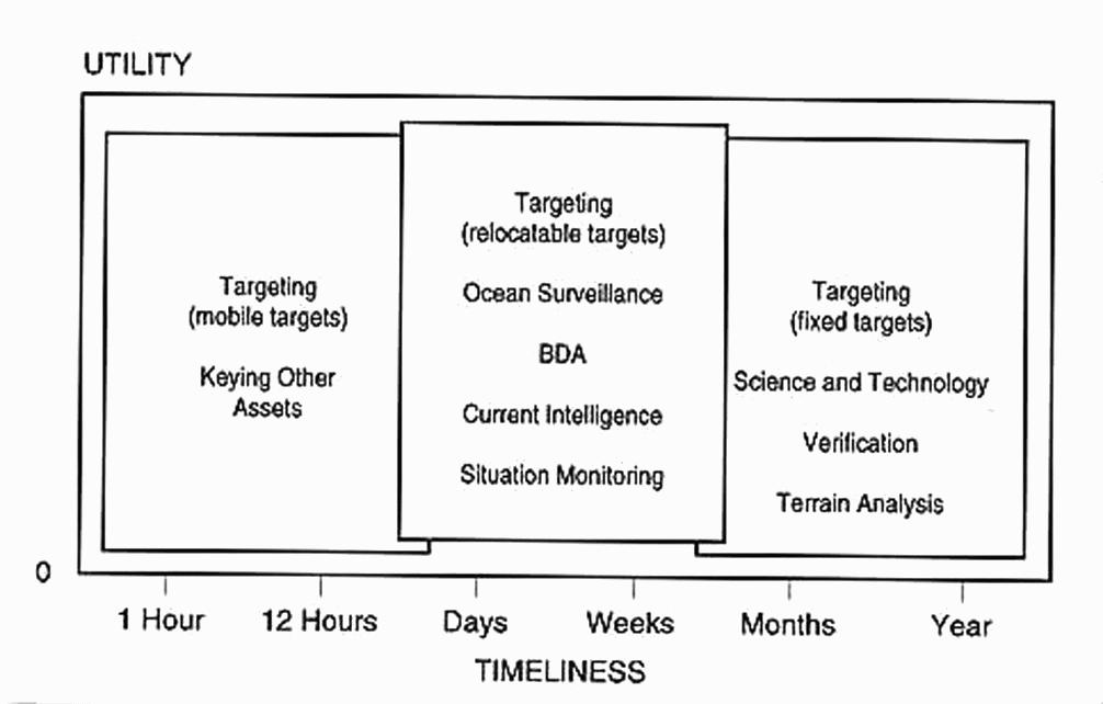
Establishing exact boundaries in terms of timeliness requirements for such tasks as ocean and wide-area surveillance and bomb damage assessment (BDA) (fig. 5.3) depends as much on the scenario being considered as on the nature of the analytical task. Wide-area surveillance in search of military construction sites (such scarring is particularly visible where large amounts of earth are being moved—e.g., the construction of new intercontinental ballistic missile [ICBM] bases or sites) may be of interest for weeks or even months after first being observed. In actual battle, however, the construction of earth berms, tank traps, and minefields may require data delivery on the order of several hours at most. Similarly, BDA is most useful when performed soon after the bombs are delivered and before the next mission is launched. Yet, this information is still valuable many hours or even days after the imagery is acquired, particularly if other factors—such as bad weather or heavy air defenses—preclude the information being gathered by more traditional means (i.e., reconnaissance aircraft). Ocean surveillance is equally sensitive to actual mission needs. For example, the determination of sea-temperature profiles for broad-area antisubmarine warfare (ASW) analysis requires data no more timely than the rate at which such synoptic features are likely to change: tens of hours or even days. But the required time lines for delivery of information on ship tracks and mine-placement activities may not exceed a few hours at best.
Except when fixed targets such as ICBM silos are involved, the required time lines for targeting are likely to be determined by the time of flight of the weapon to be delivered and the rate of motion of the target. A smart weapon, such as a homing torpedo or a cruise missile with a target-sensitive seeker, requires no more than that it be delivered to the general vicinity of its intended target to be effective. As weapon “smartness” increases, the utility of satellite imagery in directing these weapons is increasing, as is the allowable delay between image acquisition and arrival of the weapon within the range of its seeker to the target. For more sophisticated uses of satellite imagery, such as determining points of interest against which to direct more specialized sensors for detailed analysis or close-in tracking, timeliness requirements are determined by the specifics of the mission, target mobility, retargetability of the other sensors, and other specialized factors.
The timeliness of the delivery of remote-sensing data from the spacecraft to the user directly affects its utility. For current civil systems, this delay extends from days to a week or more. It is a consequence of relatively long revisit time, relatively limited capabilities to look off to the side of the satellite’s ground track, and relatively low throughput for civil image-processing systems on the ground (table 5.16). Overcoming these limitations is expensive, both in equipment cost and personnel hours.
Table 5.16
System Timeliness
(Priority Mission)
| ORDER TO IMAGE |
IMAGING THROUGH PROCESSING |
DELIVERY | TOTAL | |
|---|---|---|---|---|
| LANDSAT (16-DAY REVISIT) |
2-17 | 3 | 1 | 6-21 |
| SPOT (26-DAY REVISIT) (2-5 WITH TASKING) |
3-6 | <1 | (FROM TOULOUSE, FRANCE) |
11-14 |
| ALMAZ (1-4 WITH TASKING) |
2-5 | 1-2 | 6-7 (AIR DELIVERY) |
9-14 |
| RADARSAT (16 DAY-EQUATOR) (3 DAY-HIGH LATITUDE) (1 DAY-ARCTIC) |
1/2-16 | 1/6a | — | 1-17 |
| ERS (European Space
Agency) (35-DAY REVISIT) |
1-35 | 1/8b | — | 1-35 |
a CLAIM FOUR HOURS FROM OVERPASS TO DATA DELIVERY
b CLAIM THREE HOURS FOR "FAST DELIVERY" PRODUCTS
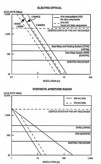
Civil space-based, remote-sensing systems operate with a combination of relatively high ground resolution and relatively rapid data-delivery times (fig. 5.4). This is due in part to an increase in satellite and sensor capabilities and in part to expanding infrastructures, including relay satellites enabling satellites to transmit data in real time to virtually any point on the earth’s surface, as well as more capable image-processing and data-transmission systems. It is the synergistic combination of these improvements that will allow the next generation of civil remote-sensing satellites to perform increasingly sensitive military functions.
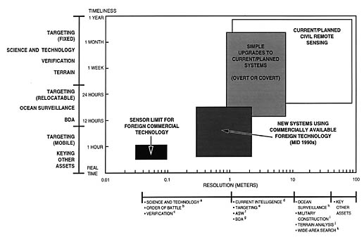
aWith sufficiently high resolution, a trained image
interpreter can perform analysis of military equipment otherwise limited to close-up
inspection. Such so-called science-and-technology analyses include measuring the
dimensions of antennas, determining vehicle weight from wheel and track impressions,
and estimating equipment performance from maintenance and service patterns.
bA primary task of the military intelligence analyst is to determine
the location and size of opposing forces. With sufficient detail available, an
analyst can also determine the type and even the identity of those forces. The
combination of all these factors—the order of battle—reveals virtually
all that a commander must know before planning an engagement.
cArms agreements place severe requirements on analysis. The use of
national technical means such as changes as the dimensions of an ICBM silo entail
achieving ground resolution on the order of inches.
dDistinguishing between general types of aircraft on the ground,
identifying tanks in a column of vehicles, and determining whether silo doors are
open or closed are all examples of current intelligence functions that can be
performed at resolutions of no greater than one meter (about three feet).
eThe availability of smart weapons means that a commander need not know
the precise location of a target—only that it is out from cover and within the
range of the assigned weapon's seeker. Civil space systems can provide this
information.
fA classic example of the use of remote-sensing data by the Navy is to
search for wakes and wave trains, surface disturbances left by periscope or antennas,
and thermal boundaries of ocean currents. This information can be derived from civil
sources.
gAlthough BDA gained widespread usage in Operation Desert Storm, the
mission has driven the development of many military surveillance and reconnaissance
systems. It refers to the need to determine whether a target has been damaged and,
if so, to what degree. Desert Storm saw the first use of civil space systems in
this role. Most BDA can be performed at no finer than one-meter resolution.
hLocating ships at sea or large battle groups in the open ocean is a
task well within the capability of current remote-sensing systems.
iRoads, revetments, runways, and other large-scale, earth-moving projects
leave large areas os acarred or displaced earth. Such features are among the
clearest indications of military construction activities and are easily observed
with civil remote-sensing systems.
jCombining spectral data with panchromatic imagery enables an analyst to
locate swamps and bogs distinguish heavily forested areas from lightly forested areas,
and locate barriers such as canyons and steep hillsides. Such information is vital
for planning engagements and positioning forces.
kCivil systems are deliberately designed to provide "synoptic coverage"
or large-scene sizes. The military analogue of this feature is "wide-area search."
Operation Desert Storm clearly illustrated the military utility of civil space systems. Coarse-resolution imagery from European weather satellites and the US National Oceanic and Atmospheric Administration (NOAA) geostationary operational environmental satellites (GOES) proved useful in assessing the likelihood of chemical attacks by the Iraqis and predicting potential dispersion paths of chemical and biological weapons (table 5.17).
Table 5.17
Some Uses of Civil Space Systems during Operation Desert Storm(U)
SPOT image maps) - Plotting major tank/tracked-vehicle movements - Bomb damage assessment - Aircraft strike mission simulation and planning |
LANDSAT and SPOT data, with resolution of 10 to 30 meters, proved useful for such applications as generating updated maps and BDA, plotting major movements of armored vehicles, and simulating approaches for pilots (table 5.17). The US Defense Mapping Agency purchased, from SPOT Image alone, $5.7 million worth of imagery to update digital maps used by troops in forward areas in aircraft and weapons-navigation systems. Incorporating SPOT off-nadir imagery into mission-planning systems enabled pilots to rehearse strike missions on three-dimensional computer reconstitutions of the target areas. A specific example is the detailed preflight mission planning and simulation in preparation for coalition aircraft’s delivery of precision guided weapons on the Mina al Ahmadi oil complex, which Iraqi forces had turned on to pump oil into the Persian Gulf.
During Desert Storm, coalition forces made use of standard civil SPOT imagery to assist in BDA missions. Images of Baghdad were taken by the French SPOT system with 10-meter resolution. An image taken on 19 February 1991, before coalition attacks, shows three intact bridges, while an image taken on 10 March 1991, after a coalition air raid, shows that two of the three bridges have been cut. Similar imagery is available from LANDSAT (US), India Remote Sensing (IRS), Earth Remote Sensing (ERS—European Space Agency), Japan Earth Remote Sensing (JERS), and RADARSAT (Canada), and will soon be available from ADEOS (Japan), China/Brazil Earth Remote Sensing (CBERS), and several commercial US systems.
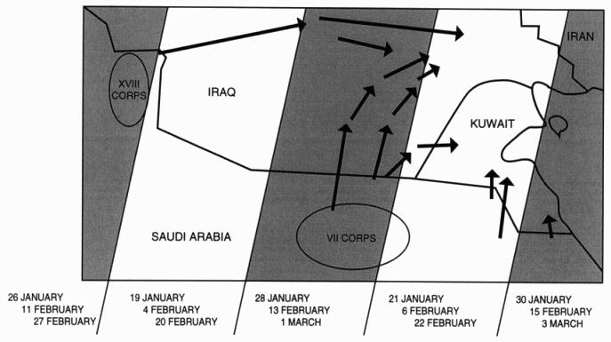
Saddam Hussein might have benefited considerably if the Iraqi military had had access to a LANDSAT-type system during Desert Storm. Specifically, because resolution of a LANDSAT-type system is sufficient to detect corps-sized deployments and because LANDSAT actually passed over the area in question at least three times from 17 January to 28 February 1991, Iraq could have detected the presence of US Army VII and XVIII Corps in their “jump-off” deployment areas in the Iraqi far-right flank (fig. 5.5). As the commander of US Space Command noted, “During Desert Storm, the allied coalition was able to covertly reposition forces immediately before the ground combat phase began only because the Iraqis did not have an aerial surveillance capability. This move allowed General Schwarzkopf to completely surprise Iraqi ground forces and minimize allied casualties. We could not have managed this against an adversary equipped with reconnaissance satellites.”
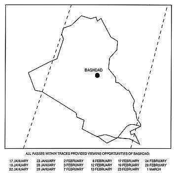
A senior Air Force official noted that SPOT and LANDSAT provided “the only source of wide-area synoptic coverage” during the Gulf War. Such synoptic coverage is essential for BDA. A SPOT-type civil system could have assisted in the coalition BDA mission against critical targets in a concentrated area such as Baghdad. Because of its off-nadir capability, SPOT is capable of imaging Baghdad during any track within the two dotted lines of figure 5.6. During the Desert Storm air campaign, SPOT made actual passes over the tracks located within these dotted lines on the dates cited; if specifically tasked to do so, it could have imaged Baghdad 18 times.
An analysis of the relative efficiency of civil satellites and search aircraft for detecting aircraft carriers in proximity of the Falkland Islands (fig. 5.7) assumed that no clouds were present and that carriers maneuvered randomly in the deployment area, not avoiding satellites (hence, each look is independent, and binomial statistics apply). The analysis showed (1) that at this latitude, the increased coverage per pass of LANDSAT is almost identically compensated for by the greater number of accessible passes of SPOT (due to taskability) and (2) that neither system approaches the performance of a standard aircraft search. However, this analysis was limited to two satellite systems. One result of the proliferation of imagery systems is that, in the near future, as many as a dozen satellites may be involved in such a search, significantly improving the ability to detect relocatable targets.
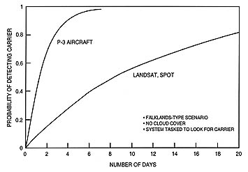
Figure 5.5 evaluated the potential impact of Iraqi access to a LANDSAT-type, civil remote-sensing system during the Gulf War. That scenario raises critical questions about a future implication resulting from the accelerating proliferation of foreign remote-sensing systems and ground stations. Major troop movements will become very difficult to conceal from a potential adversary.
One binomial analysis of civil remote-sensing systems assumed that a potential adversary would have access to more than one of the systems. It also assumed a Desert Storm–type scenario (events detectable by systems with resolutions of 10–20 meters) at midlatitude in 1995.
The analysis reached a twofold conclusion. First, if an adversary had access to all civilian remote-sensing systems (fig. 5.8, dotted line), he would have a 50 percent probability of detecting an event that lasted at least half a day and a 100 percent probability of detecting an event that lasted for two-and-one-half days (60 hours). Second, even if all US and allied systems were removed from enemy access, the probability does not demonstratively improve (fig. 5.8, solid line). That is, he would have a 50 percent probability of detecting an event that lasted one day and a 100 percent probability of detecting an event that lasted two-and-one-half days.
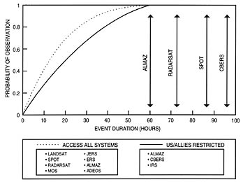
The systems that are most problematic are the ALMAZ and RADARSAT (Canadian) systems with their day/night and all-weather capabilities. The one system that will be the most problematic is the ALMAZ system, which is in Russian hands.
Clearly, a wide international proliferation of satellite imagery systems is taking place. These systems are increasingly capable in the areas of resolution, spectral coverage, revisit time, and data-delivery time. Data from the systems has significant military utility for BDA, current intelligence, change detection, targeting, and surveillance. Rapid revisit, rapid data delivery, and day/night, all-weather capabilities may do more to boost the military threat of these systems than improved resolution. Finally, high-performance systems can be built without access to US technology, unilateral controls are likely to be ineffective, and key component technologies are almost all dual use.